A Guide For Driving LED Matrices

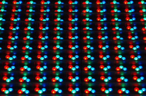
Building an LED matrix is a fun project, but it can be a bit of a pain. Usually it starts with hand-soldering individual LEDs and resistors together, then hooking them up to rows and columns so they can be driven by a microcontroller of some sort. That’s a lot of tedious work, but you can order an LED matrix pre-built to save some time and headache. You’ll still need a driver though, and while building one yourself can be rewarding there are many pitfalls and trade-offs to consider when undertaking that project as well. Or, you can consider one of a number of drivers that [deshipu] has outlined in detail.

The hangups surrounding the driver board generally revolve around the issue of getting constant brightness from LEDs regardless of how many in the row or column are illuminated at one time. Since they are typically driven one row or column at a time, the more that are on the lower the brightness each LED will have. Driver boards take different approaches to solving this problem, which usually involve a combination of high-speed scanning of the matrix or using a constant-current source in order to eliminate the need for resistors. [deshipu] outlines four popular chips that achieve these purposes, and he highlights their pros and cons to help anyone looking to build something like this.

Most of these boards will get you to an 8×8 LED matrix with no problem, with a few going a few pixels higher in either direction. That might be enough for most of our needs, but for something larger you’ll need other solutions like the one found in this 64×32 LED matrix clock. There are also even more complicated drivers if you go into extra dimensions.

Photo credit: Komatta [Public domain], from Wikimedia Commons

I’m Sorry, Alexander, I’m Afraid I Can’t Do That

Getting people to space is extremely difficult, and while getting robots to space is still pretty challenging, it’s much easier. For that reason, robots and probes have been helping us explore the solar system for decades. Now, though, a robot assistant is on board the ISS to work with the astronauts, and rather than something impersonal like a robot arm, this one has a face, can navigate throughout the ship, and can respond to voice inputs.

The robot is known as CIMON, the Crew Interactive Mobile Companion. Built by Airbus, this interactive helper will fly with German astronaut Alexander Gerst to test the concept of robotic helpers such as this one. It is able to freely move about the cabin and can learn about the space it is in without being specifically programmed for it. It processes voice inputs similarly to a smart phone, but still processes requests on Earth via the IBM Watson AI. This means that it’s not exactly untethered, and future implementations of this technology might need to be more self-contained for missions outside of low Earth orbit.

While the designers have listened to the warnings of 2001 and not given it complete control of the space station, they also learned that it’s helpful to create an interactive robot that isn’t something as off-putting as a single creepy red-eye. This robot can display an interactive face on the screen, as well as use the same screen to show schematics, procedure steps, or anything else the astronauts need. If creepy design is more your style though, you can still have HAL watching you in your house.

Thanks to [Marian] for the tip!

Continue reading “I’m Sorry, Alexander, I’m Afraid I Can’t Do That”

Agilent LCR Meter Teardown

Since 1999, one of the more popular manufacturers of test equipment has been Agilent, the spun-off former instrument division of Hewlett-Packard. From simple multimeters to fully-equipped oscilloscopes, they have been covering every corner of this particular market. And, with the help of [Kerry Wong] and his teardown of an Agilent LCR meter, we can also see that they’ve been making consistent upgrades to their equipment as well.

The particular meter that [Kerry] took apart was an Agilent U1731B, a capable LCR (inductance, capacitance, resistance) meter. He had needed one for himself and noted that while they’re expensive when new, they can be found at a bargain used, but that means dealing with older versions of hardware. For example, his meter uses an 8-bit ADC while the more recent U1733 series uses a 24-bit ADC. The other quality of this meter that [Kerry] made special note of was how densely populated the circuit board is, presumably to save on the design of a VLSI circuit.

While we don’t claim to stump for Agilent in any way, it’s good to know that newer releases of their equipment actually have improved hardware and aren’t just rebadged or firmware-upgraded versions of old hardware with a bigger price tag attached. Also, there wasn’t really any goal that [Kerry] had in mind besides sheer curiosity and a willingness to dive deep into electronics details, as those familiar with his other projects know already.

Growing Your Own Insulation

The latest craze in revolutionary materials science is no longer some carbon nanotube, a new mysterious alloy, or biodegradeable plastic. It seems as though a lot of new developments are coming out of the biology world, specifically from mycologists who study fungi. While the jury’s still out on whether or not it’s possible to use fungi to build a decent Star Trek series, researchers have in fact been able to use certain kinds of it to build high-performing insulation.

The insulation is made of the part of the fungus called the mycelium, rather than its more familiar-looking fruiting body. The mycelium is a strand-like structure of fungus which grows through materials in order to digest them. This could be mulch, fruit, logs, straw, crude oil, or even live insects, and you might have noticed it because it’s often white and fuzzy-looking. The particular type of mycelium used here is extremely resistant to changes in temperature so is ideal for making insulation. As a bonus, it can be grown, not manufactured, and can use biological waste products as a growing medium. Further, it can grow to fit the space it’s given, and it is much less environmentally harmful than existing forms of insulation.

As far as performance is concerned, a reporter from the BBC tested it in an interesting video involving a frozen chocolate bar and a blowtorch, discovering also that the insulation is relatively flame-retardant. Besides insulation, though, there are many more atypical uses of fungi that have been discovered recently including pest control and ethanol creation. They can also be used to create self-healing concrete.

Thanks to [Michael] for the tip!

Photo of fungal mycelium: Tobi Kellner [CC BY-SA 3.0]

3D Printer Warning: Heating Plastic To High Temps Is Not Healthy

If you’ve ever tried to cut a piece of acrylic with a tool designed to cut wood or metal, you know that the plastic doesn’t cut in the same way that either of the other materials would. It melts at the cutting location, often gumming up the tool but always releasing a terrible smell that will encourage anyone who has tried this to get the proper plastic cutting tools instead of taking shortcuts. Other tools that heat up plastic also have this problem, as Gizmodo reported recently, and it turns out that the plastic particles aren’t just smelly, they’re toxic.

The report released recently in Aerosol Science and Technology (first part and second part) focuses on 3D printers which heat plastic of some form or other in order to make it malleable and form to the specifications of the print. Similar to cutting plastic with the wrong tool, this releases vaporized plastic particles into the air which are incredibly small and can cause health issues when inhaled. They are too small to be seen, and can enter the bloodstream through the lungs. The study found 200 different compounds that were emitted by the printers, some of which are known to be harmful, including several carcinogens. The worst of the emissions seem to be released when the prints are first initiated, but they are continuously released throuhgout the print session as well.

Perhaps it’s not surprising that aerosolized plastic is harmful to breathe, but the sheer magnitude of particles detected in this study is worth taking note of. If you don’t already, it might be good to run your 3D printer in the garage or at least in a room that isn’t used as living space. If that’s not possible, you might want to look at other options to keep your work area safe.

Thanks to [Michael] for the tip!

High Voltage Measurement Is Shockingly Safe

With the right equipment and training, it’s possible to safely work on energized power lines in the 500 kV range with bare hands. Most of us, though, don’t have the right equipment or training, and should take great care when working with any appreciable amount of voltage. If you want to safely measure even the voltages of the wiring in your house there’s still substantial danger, and you’ll want to take some precautions like using isolated amplifiers.

While there are other safe methods for measuring line voltage or protecting your oscilloscope, [Jason]’s isolated amplifier method uses high voltage capacitors to achieve isolation. The input is then digitized, sent across the capacitors, and then converted back to an analog signal on the other side. This project makes use of a chip from TI to provide the isolation, and [Jason] was able to build it on a perfboard while making many design considerations to ensure it’s as safe as possible, like encasing high voltage sections in epoxy and properly fusing the circuit.

[Jason] also discusses the limitations of this method of isolation on his site, and goes into a lot of technical details about the circuit as well. It probably wouldn’t get a UL certification, but the circuit performs well and even caught a local voltage sag while he was measuring the local power grid. If this method doesn’t meet all of your isolation needs, though, there are a lot of other ways to go about solving the problem.

Analog Clock Goes Digital, Or Vice Versa

Designing a good clock takes a lot of considerations. It’s not just hands, faces, and numbers anymore; there are also word clocks, electronic clocks, marble clocks, or water clocks, and just about anything else imaginable can be used to tell time. Of course, electronic clocks are great for their versatility, and this one shows off an analog-looking clock that is (of course) digital, leveraging all of the perks of analog with all of the upsides of digital electronics.

One of the key design considerations that [Sasa] had while building this piece was that it needed to be silent. LEDs certainly fit that description, so the decision was made to go with an WS2812b ring. It runs using a STM ST32F103 Nucleo board (and a cheaper version of it in later versions of this clock) which shows a red LED for the current hour, yellow LEDs for the traditional analog clock divisions, a green LED for the current minute, and glows the rest of the LEDs up to the current minute with a rainbow pattern.

This is a really clean, simple build with good design at its core, and would be easy to replicate if you’re looking for an eye-catching clock to build. As a bonus, all of the schematics and code are available on the project site, so everything you need is there. If you’re looking for more inspiration, there are some clocks that are even more unique, like this marble clock that is a work of art — but is anything but silent.