This Is How The Fonz Would Play MP3s

Here at Hackaday, we love to see old hardware treated with respect. A lovingly restored radio or TV that’s part of our electronic heritage is a joy to behold, and while we understand the desire to stream media from a funky retro case, it really grates when someone throws away the original guts to make room for new electronics.

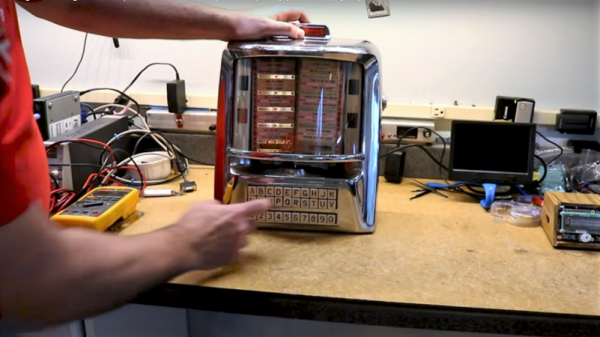
Luckily, this Seeburg jukebox wall remote repurposing is not one of those projects. [Scott M. Baker] seems to have an appreciation for the finer things, and when he scored this classic piece of Mid-Century Americana, he knew just what to do. These remotes were situated around diners and other hangouts in the 50s and 60s and allowed patrons to cue up some music without ever leaving their seats. They were real money makers back in the day, and companies put a lot of effort into making them robust and reliable.

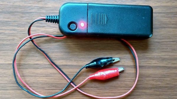
[Scott]’s first video below shows the teardown of this unit; you can practically smell the old transformer and motor windings. His goal in the second video was to use the remote to control his Raspberry Pi jukebox; he wisely decided to leave everything intact and use the original electromechanically generated pulses to make selections. His analysis led to a nicely executed shield for his Pi which conditions the pulses and imitates coin drops; happily, the coin mechanism still works too, so you can still drop a quarter for a tune.

The remote is working well now, but [Scott] still needs to finish up a few odds and ends to bring this one home. But we love the look and the respect for tradition here, as we did when this juke got a Raspberry Pi upgrade to imitate a missing wall remote.

Continue reading “This Is How The Fonz Would Play MP3s”

Putting A Poor Man’s Vector Analyzer Through Its Paces

If anything about electronics approaches the level of black magic, it’s antenna theory. Entire books dedicated to the subject often merely scratch the surface, and unless you’re a pro with all the expensive test gear needed to visualize what’s happening, the chances are pretty good that your antenna game is more practical than theoretical. Not that there’s anything wrong with that — hams and other RF enthusiasts have been getting by with antennas that work without really understanding why for generations.

But we’re living in the future, and the tools to properly analyze antenna designs are actually now within the means of almost everyone. [Andreas Spiess] recently reviewed one such instrument, the N1201SA vector impedance analyzer, available from the usual overseas sources for less than $150. [Andreas]’s review does not seem to be sponsored, so it seems like we’re getting his unvarnished opinion; spoiler alert, he loves it. And with good reason; while not a full vector network analyzer (VNA) that will blow a multi-thousand dollar hole in your wallet, this instrument looks like an incredible addition to your test suite. The tested unit works from 137 MHz to 2.4 GHz, so it covers the VHF and UHF ham bands as well as LoRa, WiFi, cell, ISM, and more. But of course, [Andreas] doesn’t just review the unit, he also gives us a healthy dose of theory in his approachable style.

[The guy with the Swiss accent] has been doing a lot of great work these days, covering everything from how not to forget your chores to reverse engineering an IoT Geiger counter. Check out his channel — almost everything he does is worth a watch.

Continue reading “Putting A Poor Man’s Vector Analyzer Through Its Paces”

Eavesdropping On A VGA Monitor’s Conversations

Did you ever wonder what your monitor and your computer are talking about behind your back? As it turns out, there’s quite a conversation going on while the monitor and the computer decide how to get along, and sniffing out VGA communications can reveal some pretty fascinating stuff about the I²C protocol.

To reverse engineer the configuration information exchanged between a VGA monitor and a video card, [Ken Shirriff] began by lopping a VGA cable in two. The inside of such cables is surprisingly complex, with separate shielding wires for each color and sync channel and a host of control wires, all bundled in multiple layers of shielding foil and braid to reduce EMI. [Ken] identified the clock and data lines used for the I²C interface and broke those out into a PocketBeagle for analysis using the tiny Linux machine’s I²C tools.

With a Python script to help decode the monitor’s Extended Display Identification Data (EDID) data, [Ken] was able to see everything the monitor knows about itself — manufacturer, serial number, all the supported resolution modes, and even deprecated timing and signal information left over from the days when CRTs ruled the desktop. Particularly interesting are the surprisingly limited capabilities of a VGA display in terms of color reproduction, as well as [Ken]’s detailed discussion on the I²C bus in general and how it works.

We always enjoy these looks under the hood that [Ken] is so good at, and we look forward to his reverse engineering write-ups. His recent efforts include a look at core memory from a 50-year old mainframe and reverse engineering at the silicon level.

A Brushless Motor On A PCB, Made From PCB

At Hackaday, we really appreciate it when new projects build on projects we’ve featured in the past. It’s great to be able to track back and see what inspires people to pick up someone else’s work and bring it to the next level or take it down a totally new path.

This PCB brushless motor is a great example of the soft collaboration that makes the Hackaday community so powerful. [bobricius] says he was inspired by this tiny PCB BLDC when he came up with his design. His write-up is still sparse at this point, but it looks like his motor is going to be used to drive a small robot. As with his inspiration, this motor has the stator coils etched right into the base PCB. But there are some significant improvements, like increasing the stator coil count from six to eight, as well as increasing the overall size of the motor. [bobricius] has also done away with the 3D-printed rotor of the original, opting to fabricate his rotor from stacked PCBs with cutouts for 5-mm neodymium magnets. We like the idea of using the same material throughout the motor, and it also raises the potential for stacking a second stator on the other side of the rotor, which might help mechanically and electrically. Even still, the prototype seems to hold its own in the video below.

This is [bobricius]’ second entry in the 2018 Hackaday Prize so far, after his not-a-Nixie tube display. Have you entered anything yet? Get to it! Prizes, achievements, and glory await.

Continue reading “A Brushless Motor On A PCB, Made From PCB”

It’s A Nixie! It’s A VFD! No, It’s A Custom LED Display In A Tube

Like the look of Nixies but they just seem a little overdone? Or perhaps you just don’t want the hassles of a high-voltage power supply? Then maybe these faux-Nixie LED “tube” displays will find a way into your next clock build.

For his 2018 Hackaday Prize entry, [bobricius] decided that what the world needs is a Nixie that’s not a Nixie. To that end, each display is formed by seven surface-mount LEDs soldered to a seven-segment shaped PCB and slipped into a glass tube. The LEDs are in 4014 packages so they’re only 4 millimeters long, but what they lack in size they make up for in brightness. We’re not sure if it’s a trick of the camera, but the LEDs certainly seem to put off a bluish glow that’s reminiscent of vacuum-fluorescent displays — it’s like a Nixie and a VFD all rolled up in one package.  The current case, which hides the clock circuitry on the lower part of the PCB, is just plastic, but this would look spiffy in a fine wooden case.

Could this be another Nixie tube killer that never was? Perhaps, but wherever it ends up, we like the look of it, and we’re glad it’s one of the early Hackaday Prize entries. Have you got something to enter in the greatest hardware competition on Earth? If not, get cracking!

Handy Continuity Tester Packs Multiple Modes Into A Tiny Package

From Leatherman multitools to oscilloscopes with built-in signal generators and protocol analyzers, there seems no end to tools with multiple personalities. Everybody loves multitaskers because they make it feel like you’re getting more bang for your buck, and in most cases that’s true. But a jack of all trades is seldom master of any, and there are times when even the humble multimeter isn’t the best tool for the job.

With that in mind, [sidsingh] has developed what we think is a very nice dedicated continuity tester. With a goal of using only parts on hand, he had to think small to fit everything into the case he had. So he started with a PIC10LF322 to support all the flavors of continuity testing he wanted to support. In addition to straight continuity, the tester can handle diode testing, detecting shorted or open diodes and even differentiating between regular and Schottky diodes. It also has an LED test mode and an interesting “discontinuity” testing mode — it only sounds its buzzer when continuity is broken. The video below shows that mode in action for finding intermittent cable faults, along with all the other modes.

For an ostensibly single-purpose tool, this tester still manages to pack a lot of tests into one very compact package. Simpler continuity testers are good, too — check out this cheap dollar store build, or this slightly more complicated unit based on an ATtiny85.

Continue reading “Handy Continuity Tester Packs Multiple Modes Into A Tiny Package”

Lasers, Mirrors, And Sensors Combine In An Optical Bench Game

Who would have thought you could make a game out of an optical bench? [Chris Mitchell] did, and while we were skeptical at first, his laser Light Bender game has some potential. Just watch your eyes.

The premise is simple: direct the beam of a colored laser to the correct target before time runs out. [Chris] used laser-cut acrylic for his playfield, which has nine square cutouts arranged in a grid. Red, green, and blue laser pointers line the bottom of the grid, with photosensors and RGB LEDs lining the grid on the other three sides. Play starts with a random LED lighting up in one of the three colors, acting as a target. The corresponding color laser comes on, and the player has to insert mirrors or pass-through blocks in the grid to create a path to the target. The faster you hit the CdS cell, the higher your score. It’s simple, but it looks really engaging. We can imagine all sorts of upgrades, like lighting up two different targets at once, or adding a beamsplitter block to hit two targets with the same color. Filters and polarizers could add to the optical fun too.

We like builds that are just for fun, especially when they’re well-crafted and have a slight air of danger. The balloon-busting killbots project we featured recently comes to mind.

Continue reading “Lasers, Mirrors, And Sensors Combine In An Optical Bench Game”