Milspec Teardown: CP-142 Range Computer

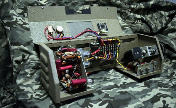
As some of my previous work here at Hackaday will attest to, I’m a big fan of World War II technology. Something about going in with wooden airplanes and leaving with jet fighters and space capable rockets has always captivated me. So when one of my lovingly crafted eBay alerts was triggered by something claiming to be a “Navy WWII Range Computer”, it’s safe to say I was interested.

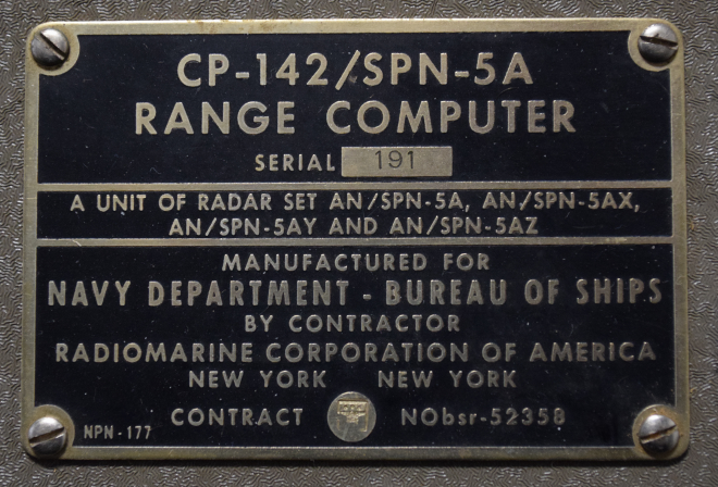
Not to say I had any idea of what the thing was, mind you. I only knew it looked old and I had to have it. While I eagerly awaited the device to arrive at my doorstep, I tried to do some research on it and came up pretty much empty-handed. As you might imagine, a lot of the technical information for hardware that was developed in the 1940’s hasn’t quite made it to the Internet. Somebody was selling a technical manual that potentially would have covered the function of this device for $100 on another site, but I thought that might be a bit excessive. Besides, where’s the fun in that?

I decided to try to decipher what this device does by a careful examination of the hardware, consultation of what little technical data I could pull up on its individual components, and some modern gear. In the end I think I have a good idea of how it works, but I’d certainly love to hear if there’s anyone out there who might have actually worked with hardware like this and could fill in any blanks.

Continue reading “Milspec Teardown: CP-142 Range Computer”

Rejecting Microsoft’s Phaseout Of The Kinect

You might not be aware unless you’re up on the latest gaming hardware, but Microsoft is trying to kill the Kinect. While the Xbox One famously included it as a mandatory pack-in accessory at launch (this was later abandoned to get the cost down), the latest versions of the system don’t even have the proprietary port to plug it in. For a while Microsoft was offering an adapter that would let you plug it into one of the console’s USB ports, but now even that has been discontinued. Owners of the latest Xbox One consoles who still want to use the Kinect are left to find an adapter on eBay, where the prices have naturally skyrocketed.

Recently [Eagle115] decided to open up his Kinect and see if he couldn’t figure out a way to hook it up to his new Xbox One. The port on the Kinect is a USB 3.0 B female, but it requires 12V to operate. The official Kinect adapter took the form of a separate AC adapter and a “tap” that provided the Kinect with 12V over USB, so he reasoned he could pop open the device and provide power directly to the pads on the PCB.

[Eagle115] bought a 12V wall adapter and a USB 3.0 B cable and got to work. Once the Kinect was popped open, he found that he needed to supply power on pin 10 (which is helpfully labeled on the PCB). There’s just enough room to snake the cable from the AC adapter through the same hole in the case where the the USB cable connects.

With the Kinect getting 12V from the AC adapter, the Xbox has no problem detecting it as if you were using the official adapter. At least for now, they haven’t removed support for the Kinect in the Xbox’s operating system.

The Kinect has always been extremely popular with hackers (it even has its own category here on Hackaday), so it’s definitely sad to see that Microsoft is walking away from the product. The community will no doubt continue pulling off awesome hacks with it; but it’s looking increasingly likely we won’t be getting a next generation Kinect.

[via /r/DIY]

The Fine Art Of Acid Etching Brass

If you were building a recreation of the James Watt micrometer, where would you start? If you’re [rasp], the answer would be: “Spend a year trying to find the best way to make etched brass discs.” Luckily for us, he’s ready to share that information with the rest of the world. While it’s rather unlikely anyone else is working on this specific project, the methods he details for getting museum-quality results on brass are absolutely fascinating.

The process starts with sanding down the bare brass and applying a layer of clear packing tape to the metal. [rasp] then covers the piece with LaserTape, which is a special tape designed to make laser-cut masks for sandblasting. But the masking principle works just as well for painting or chemical etching.

With the LaserTape in place, the piece is then put into the laser and the mask is cut out. Once cut, there’s the tedious task of peeling off all the cut pieces of tape, which [rasp] does with a dental pick. Once the pieces are pulled off, the brass is ready for its acid bath.

Anyone who’s etched their own PCB with ferric chloride will recognize these next steps. The piece is put into the acid bath and agitated every 10 minutes or so. It’s interesting to note that [rasp] places the piece in the bath upside-down, using little 3D printed “feet” to suspend the brass sheet off the bottom of the container. This allows the debris from the etching process to fall down and away from the piece. After about an hour out in the sun, the piece is pulled out of the bath and carefully washed off.

Once clean off, the piece is sprayed with black spray paint to darken up the etched areas. The moment of truth comes when the paint has dried and the layers of tape are carefully peeled back to reveal the etching. [rasp] then wet sands the piece with 1000 and 2000 grit paper, and a final pass with polishing compound brighten up the surface to a mirror-like shine. It’s quite a bit of manual labor, but the end result really is spectacular.

In the video after the break, [rasp] breaks down the entire process, including the additional machine work required to turn these brass plates into functional components of the final machine. As an added bonus, he even includes a lot of his failed attempts in an effort to keep others from making the same mistakes. Something we love to see here at Hackaday.

The process used here is similar to the snazzy brass name plates we showed earlier in the year, and has even been done without a laser using photoresist.

[via /r/DIY]

Continue reading “The Fine Art Of Acid Etching Brass”

Analyzing Hobby Motors With An Oscilloscope

We always like finding new excuses reasons to use our test equipment, so we couldn’t help but be intrigued by this tip from [Joe Mosfet]. He uses the ever-popular Rigol DS1054Z to demonstrate the differences between a handful of brushless motors when rotated by his handheld drill at a constant RPM. Not only is he able to identify a blown motor, but it allows him to visualize their specifications which can otherwise seem a bit mystifying.

One wire from each motor is used as the ground, and channels one and two are connected to the remaining wires. Despite the DS1054Z having four channels, [Joe] is actually only using two of them here. The third channel being displayed is a virtual channel created by a math function on the scope.

After wiring them up, each motor got put into the chuck of his drill and spun up to 1430 RPM. The resulting waveforms were captured, and [Joe] walks us through each one explaining what we’re seeing on the scope.

The bad motor is easy to identify: the phases are out of alignment and in general the output looks erratic. Between the good motors, the higher the Kv rating of the motor, the lower voltage is seen on the scope. That’s because Kv in the context of brushless motors is a measurement of how fast the motor will spin for each volt. The inverse is also true, and [Joe] explains that if he could spin his 2450Kv motor at exactly 2450 RPM, we should see one volt output.

Beyond demonstrating the practical side of Kv ratings, [Joe] also theorizes that the shape of the wave might offer a glimpse into the quality of the motor’s construction. He notes his higher end motors generate a nice clean sine wave, while his cheaper ones show distortion at the peaks. An interesting note, though he does stress he can’t confirm there’s a real-world performance impact.

Last year we featured a similar method for identifying bad brushless motors using a drill press and an oscilloscope, but we liked that [Joe] went through the trouble of testing multiple motors and explaining the differences in their output.

[via /r/multicopter]

Building An Arduino Smart IC Tester For $25

There’s no question that you can get a lot done with the classic multimeter; it’s arguably the single most capable tool on your bench. But the farther down the rabbit hole of hacking and reverse engineering you go, the more extravagant your testing and diagnostic gear tends to get. For some of us that’s just an annoying reality of the game. For others it’s an excuse to buy, and maybe even build, some highly specialized equipment. We’ll give you one guess as to which group we fall into here at Hackaday.

[Akshay Baweja] is clearly a member of the second group. He’s recently published a guide on building a very slick intelligent Integrated Circuit tester with a total cost of under $25 USD. Whether you’re trying to identify an unknown chip or verifying your latest parts off the slow-boat from China actually work before installing them in your finished product, this $25 tool could end up saving you a lot of time and aggravation.

[Akshay] walks readers through the components and assembly of his IC tester, which takes the form of a Shield for the Arduino Mega 2560. The custom PCB he designed and had manufactured holds the 20 Pin ZIF Socket as well as the 2.4 inch TFT touch screen. The screen features an integrated micro SD slot which is important as you need the SD card to hold the chip database.

With an IC to test inserted into the ZIF socket, the user can have the tester attempt to automatically ID the chip or can manually enter in a part number to lookup. The source code for the Arduino as well as the chip ID database is up on GitHub for anyone looking to add some more hardware to the device’s testing repertoire.

The importance of good test equipment simply cannot be overstated. Between highly specialized gear like this IC tester to classic instruments such as the oscilloscope, your bench is going to be full of weird and wonderful pieces of equipment before too long.

Continue reading “Building An Arduino Smart IC Tester For $25”

Printed Motorcycle Choke Lever Goes The Distance

We all dread the day that our favorite piece of hardware becomes so old that spare parts are no longer available for it, something about facing that mechanical mortality sends a little shiver up the hacker’s spine. But on the other hand, the day you can’t get replacement hardware is also the same day you have a valid excuse to make your own parts.

3D rendering above the 2D scan

That’s the situation [Jonathan] found himself in when the choke lever for his Suzuki motorcycle broke. New parts aren’t made for his bike anymore, which gave him the opportunity to fire up Fusion 360 and see if he couldn’t design a replacement using a 2D scan of what was left of the original part.

[Jonathan] put the original part on his flatbed scanner as well one of his credit cards to use for a reference point to scale the image when he imported it into Fusion 360. Using a 2D scanner to get a jump-start on your 3D model is a neat trick when working on replacement parts, and one we don’t see as much as you might think. A proper 3D scanner is cool and all, but certainly not required when replicating hardware like this.

The choke lever is a rather complex shape, one of those geometries that doesn’t really have a good printing orientation because there are overhangs all over the place. That combined with the fact that [Jonathan] printed at .3mm layer height for speed gives the final part an admittedly rough look, but it works. The part was supposed to be a prototype before he reprinted it at higher resolution and potentially with a stronger material like PETG, but after two years the prototype is still installed and working fine. This isn’t the first time we’ve seen a “temporary” 3D printed part become a long-term solution.


This is an entry in Hackaday’s

Repairs You Can Print contest

The twenty best projects will receive $100 in Tindie credit, and for the best projects by a Student or Organization, we’ve got two brand-new Prusa i3 MK3 printers. With a printer like that, you’ll be breaking stuff around the house just to have an excuse to make replacement parts.


Create A Discord Webhook With Python For Your Bot

Discord is an IRC-like chat platform that all the young cool kids are hanging out on. Originally intended as a way to communicate during online games, Discord has grown to the point that there are servers out there for nearly any topic imaginable. One of the reasons for this phenomenal growth is how easy it is to create and moderate your own Discord server: just hit the “+” icon on the website or in the mobile application, and away you go.

As a long-time IRC guy, I was initially unimpressed with Discord. It seemed like the same kind of stuff we’ve had for decades, but with an admittedly slick UI. After having used it for a few months now and joining servers dedicated to everything from gaming to rocket science, I can’t say that my initial impression of Discord is inaccurate: it’s definitely just a modern IRC. But I’ve also come to the realization that I’m OK with that.

But this isn’t a review of Discord or an invitation to join the server I’ve setup for my Battlefield platoon. In this article we’re going to look at how easy it is to create a simple “bot” that you can plug into a Discord server and do useful work with. Since anyone can create a persistent Discord server for free, it’s an interesting platform to use for IoT monitoring and logging by simply sending messages into the server.

Continue reading “Create A Discord Webhook With Python For Your Bot”