Look at this prototype Apple smartphone from 1993! For a long time, Apple has been in the phone game, with many failed attempts to combine a laptop screen with a phone. The most noteworthy attempt would be the Snow White phone designed around 1982, but this didn’t go to market. Apple tried again in 1993 with the Walt phone, and now we have someone willing to tear open a prototype. The guts are apparently a contemporary PowerBook (something along the lines of a PowerBook 140 or 170), which means you’re probably looking at a 68030 processor and between 2 and 8 Megabytes of RAM. The rest of the hardware looks fairly standard; SCSI drive and a fax/modem adapter. The software, though, is Hypercard. Here’s the video of the thing booting, and it’s an interesting look at the ‘computer appliance’ trend from the late 90s; once again, Apple was ahead of the curve.
Disregarding any of the implications of geopolitics of the time (as we do with these sorts of things), the Horten Ho 299 was a jet-powered flying wing that first flew in 1944. It’s in the Smithsonian now (and on display, at Dulles) and is a weird, strange, but incredibly interesting footnote in aviation history (because of the implications of geopolitics at the time, but again, we’re not going to get into that). Now the Horten flies again. A company unrelated to Herr Horten has recreated the one-man flying wing. It’s a real experimental aircraft now. Sure, it’s a piston-powered airplane, but if you want to fly something that looks even cooler than something Burt Rutan grew out of fiberglass, this is what you want.
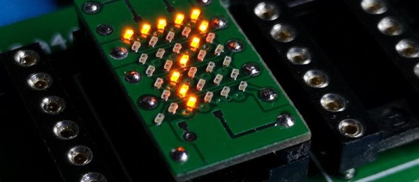
For the past few months, Hackster has been running a BadgeLove contest, now the entries are closed and the winners are here. The Badge Of All Badges is a contactless/NFC badge, the blinkiest has some awesome documentation, and the best art is directly from Pokemon Yellow.
Vinyl has made a comeback, and so far we’ve been accepting of that. The album art is better when it’s bigger, and a record is more of an experience than popping in a CD or streaming some music. There’s a reason your favorite Beatles song is the B-side of Abbey Road. What’s the next frontier of high-end audio? Reel to reel, and Thorens is making a new tape machine. First off: it costs thirteen thousand dollars. It’s a quarter inch tape, and yeah, you can totally find a machine that will play quarter inch tapes for far less money.
Due to my vocation, I am awash in press releases every day. This doesn’t give me access to technology trends, far from it. It gives me access to marketing trends. Want to know about the fog, or ‘the cloud at ground level’? The first time anyone with two brain cells saw that phrase was in an unsolicited email, and it’s in my inbox. The latest trend — and I assure you this didn’t happen last year — is advertising explicit targeted towards April 20th. 4/20 is now mainstream, because marketing decided you can sell stuff to stoners. I’m looking at an email right now that starts with, “Hi Brian, With 4/20 fast approaching I thought you’d be interested….” There’s another one for vapes. This year, 4/20 has become a consumer holiday, so this year be on the lookout for the new, innovative ways you’re being sold stuff.