What is it about tangible media? There’s just something neat about having an individual thing that represents each game, each album, each whatever. Sure, you can have a little console with a thousand games loaded on it, but what’s the fun in that?
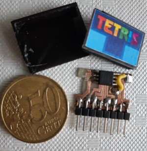 Enter the ATtinyBoy. [Bram]’s entry into the Tiny Games Contest is based on the ATtiny85, and the whole thing is smaller than a credit card. In fact, each little game cartridge contains its own ATtiny85, with the pins broken out into headers.
That is, although the schematic is based on [Billy Cheung]’s gametiny, which uses an ATtiny85 as the brain, ATtinyBoy’s brain is divided among each of the games.
This certainly checks a lot of boxes when it comes to contest rules and requirements, and it’s just awesome besides. We particularly like the custom box that holds ATtinyBoy and all his distributed knowledge. If you want to make one of your own, the schematic, code, and STLs are all available over on IO.