Hybrid Lab Power Supply From Broken Audio Amp

The lab power supply is an essential part of any respectable electronics workbench. However, the cost of buying a unit that has all the features required can be eye-wateringly high for such a seemingly simple device. [The Post Apocalyptic Inventor] has showed us how to build a quality bench power supply from the guts of an old audio amplifier.

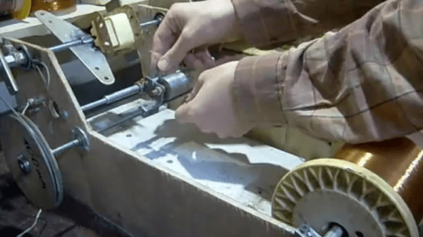
We’ve covered our fair share of DIY power supplies here at Hackaday, and despite this one being a year old, it goes the extra mile for a number of reasons. Firstly, many of the expensive and key components are salvaged from a faulty audio amp: the transformer, large heatsink and chassis, as well as miscellaneous capacitors, pots, power resistors and relays. Secondly, this power supply is a hybrid. As well as two outputs from off-the-shelf buck and boost converters, there is also a linear supply. The efficiency of the switching supplies is great for general purpose work, but having a low-ripple linear output on tap for testing RF and audio projects is really handy.

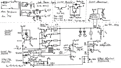
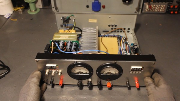
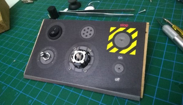
The addition of the linear regulator is covered in a second video, and it’s impressively technically comprehensive. [TPAI] does a great job of explaining the function of all the parts which comprise his linear supply, and builds it up manually from discrete components. To monitor the voltage and current on the front panel, two vintage dial voltmeters are used, after one is converted to an ammeter. It’s these small auxiliary hacks which make this project stand out – another example is the rewiring of the transformer secondary and bridge rectifier to obtain a 38V rail rated for twice the original current.

The Chinese DC-DC switching converters at the heart of this build are pretty popular these days, in fact we’re even seeing open source firmware being developed for them. If you want to find out more about how they operate on a basic level, here’s how a buck converter works, and also the science behind boost converters.

Continue reading “Hybrid Lab Power Supply From Broken Audio Amp”

DIY Coil Winding Machine Counts The Hacky Way

“Wait, was that 423 or 424?” When you’re stuck winding a transformer or coil that has more than a few hundred turns, you’re going to want to spend some time on a winding jig. This video, embedded below, displays a simple but sufficient machine — with a few twists.

The first elaboration is the addition of a shuttle that moves back and forth in sync with the main spindle to lay the windings down nice and smooth. Here, it’s tremendously simple — a piece of threaded rod and a set of interchangeable wheels that are driven by a big o-ring belt. We love the low-tech solution of simply adding a twist into the belt to swap directions. We would have way overthought the mechanism.

But then the hack is the digital counter made out of an old calculator. We’ve seen this before, of course, but here’s a great real-world application.

Thanks [Jānis] for the tip!

Continue reading “DIY Coil Winding Machine Counts The Hacky Way”

A HID For Robots

Whether with projects featured here or out in the real world, we have a tendency to focus most upon the end product. The car, solar panel, or even robot. But there’s a lot more going on behind the scenes that needs to be taken care of as well, whether it’s fuel infrastructure to keep the car running, a semiconductor manufacturer to create silicon wafers, or a control system for the robot. This project is one of the latter: a human interface device for a robot arm that is completely DIY.

While robots are often automated, some still need human input. The human input can be required all the time, or can be used to teach the robot initially how to perform a task which will then be automated. This “keyboard” of sorts built by [Ahmed] comes with a joystick, potentiometer, and four switch inputs that are all fully programmable via an Arduino Due. With that, you can perform virtually any action with whatever type of robot you need, and since it’s based on an Arduino it would also be easy to expand.

The video below and project page have all the instructions and bill of materials if you want to roll out your own. It’s a pretty straightforward project but one that might be worth checking out since we don’t often feature controllers for other things, although we do see them sometimes for controlling telescopes rather than robots.

Continue reading “A HID For Robots”

Ask Hackaday: How Do You DIY A Top-Octave Generator?

One of the great joys of Hackaday are the truly oddball requests that we sometimes get over the tip line. Case in point: [DC Darsen] wrote in with a busted 1970s organ in need of a new top-octave generator, and wondered if we could help. He had found a complicated but promising circuit online, and was wondering if there was anything simpler. I replied “I should be able to get that done with a single Arduino” and proceeded to prove myself entirely wrong in short order.

So we’re passing the buck on to you, dear Hackaday reader. Can you help [DC Darsen] repair his organ with a minimum amount of expenditure and hassle? All we need to do is produce twelve, or maybe thirteen, differently pitched square waves simultaneously.

Continue reading “Ask Hackaday: How Do You DIY A Top-Octave Generator?”

More Details On That First Home-Made Lithographically Produced IC

A few days ago we brought you news of [Sam Zeloof]’s amazing achievement, of creating the first home-made lithographically produced integrated circuit. It was a modest enough design in a simple pair of differential amplifiers and all we had to go on was a Twitter announcement, but it promised a more complete write-up to follow. We’re pleased to note that the write-up has arrived, and we can have a look at some of the details of just how he managed to produce an IC in his garage. He’s even given it a part number, the Zeloof Z1.

For ease of manufacture he’s opted for a PMOS process, and he is using four masks which he lists as the active/doped area, gate oxide, contact window, and top metal. He takes us through 66 different processes that he performs over the twelve hours of a full production run, with comprehensive descriptions that make for a fascinating run-down of semiconductor manufacture for those of us who will never build a chip of our own but are still interested to learn how it is done. The chip’s oblong dimensions are dictated by the constraints of an off-the-shelf Kyocera ceramic chip carrier, though without a wire bonding machine he’s unable to do any more than test it with probes.

You can read our reporting of his first announcement, but don’t go away thinking that will be all. We’re certain [Sam] will be back with more devices, and can’t wait to see the Z2.

First Lithographically Produced Home Made IC Announced

It is now six decades since the first prototypes of practical integrated circuits were produced. We are used to other technological inventions from the 1950s having passed down the food chain to the point at which they no longer require the budget of a huge company or a national government to achieve, but somehow producing an integrated circuit has remained out of reach. It’s the preserve of the Big Boys, move on, there’s nothing to see here.

Happily for us there exists a dedicated band of experimenters keen to break that six-decade dearth of home-made ICs. And now one of them, [Sam Zeloof], has made an announcement on Twitter that he has succeeded in making a dual differential amplifier IC using a fully lithographic process in his lab. We’ve seen [Jeri Ellsworth] create transistors and integrated circuits a few years ago and he is at pains to credit her work, but her interconnects were not created lithographically, instead being created with conductive epoxy.

For now, all we have is a Twitter announcement, a promise of a write-up to come, and full details of the lead-up to this momentous event on [Sam]’s blog. He describes both UV lithography using a converted DLP projector and electron beam lithography using his electron microscope, as well as sputtering to deposit aluminium for on-chip interconnects. We’ve had an eye on his work for a while, though his progress has been impressively quick given that he only started amassing everything in 2016. We look forward to greater things from this particular garage.

The Simplest Possible DIY Ultrasonic Levitator

We thought that making things levitate in mid-air by the power of sound was a little bit more like magic, or at least required fancy equipment. It turns out that you can do it yourself easily enough with parts that any decent hacker’s closet should have in abundance: a motor-driver IC, two ultrasonic distance pingers, and a microcontroller. This article shows you how (translated here, scroll down).

But aside from a few clever tricks, there’s not that much to show. The two HC-SR04 ultrasonic distance sensors are standard fare, and are just being used as a cheap source of 40 kHz transducers. The circuit uses a microcontroller, but any source of 40 kHz square waves should suffice. Those of you who could do that with a 555 (or a Raspberry Pi), this one’s for you! A stepper motor driver bumps up the voltage applied to the transducers, but you could use plain-vanilla transistors as well.

It’s all the little details that count, however. You need to position the two ultrasonic drivers fairly precisely to create a standing wave, and while you can start at 8.25 mm and trial-and-error it, the article demonstrates using an oscilloscope to align the capsules by driving one and reading the signal out of the other and tweaking them until they’re in phase. Clever!

The author also takes the ultrasonic-transparent grille from one of the unused receivers and uses it as a spoon to help position the styrofoam bits in the sound waves. We always wondered how you’d do that!

It turns out that it’s easy to make a DIY ultrasonic levitation desk toy, and none of the parts are expensive or critical. The missing ingredient is just the gumption to try it, and now we have that, too.

As cool as they are, the HC-SR04 modules aren’t perfect for all distance sensing applications. Here’s everything you need to know about them, including hacks to make them work up-close. And since HC-SR04 sensors come cheapest in ten-packs, you’ll be wondering what you’re going to do with the other eight. That problem has apparently also been solved.