You’ve got to watch out for Loki — he’s a trickster, after all, and he might make you think this semi-cyberdeck mash-up machine is named after him, when the backstory on this build is more interesting than anything in the current Marvel scene.
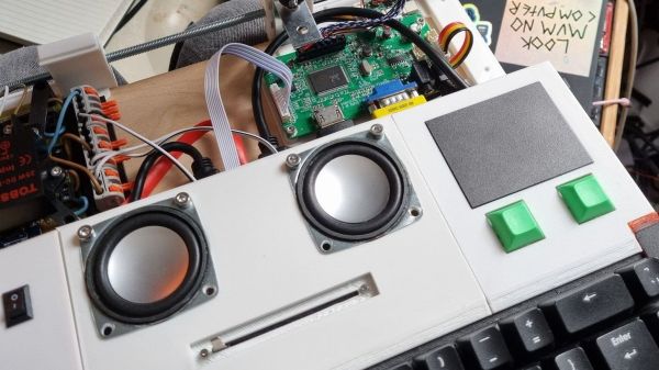
According to [Steve Anderson], Loki was the name of a mocked-up machine that Sinclair teased in the mid-1980s as a competitor for the Amiga. [Steve] coveted the vaporware machine and never quite got over it, but rather than pine for something that never existed, he created his own Loki. He only loosely qualifies the machine as a cyberdeck — it has some features of the genre, like a Raspberry Pi and a cast-off iPad screen for a display, but isn’t really intended to be as portable as a real cyberdeck. To scratch his Sinclair itch, the machine also includes a ZX Uno, which is an FPGA emulator of the Sinclair Spectrum. The keyboard is hand-wired using mechanical switches, and is backed up by a Pico running custom software so it can talk both USB and PS/2.
[Steve] has much more detail on Loki and his other cyberdeck builds over on his blog, which you should probably check out. Somewhat surprisingly, it doesn’t look like he’s entered Loki in our new Cyberdeck Contest that just launched. Hopefully that’s just an oversight.