Transmitting MIDI Signals With XBEE

What do you do when you want to rock out on your keytar without the constraints of cables and wires? You make your own wireless keytar of course! In order to get the job done, [kr1st0f] built a logic translator circuit. This allows him to transmit MIDI signals directly from a MIDI keyboard to a remote system using XBEE.

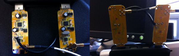
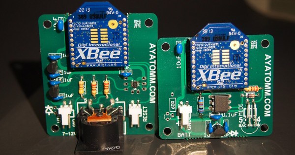
[kr1st0f] started with a MIDI keyboard that had the old style MIDI interface with a 5 pin DIN connector. Many new keyboards only have a USB interface, and that would have complicated things. The main circuit uses an optoisolator and a logic converter to get the job done. The MIDI signals are converted from the standard 5V logic to 3.3V in order to work with the XBEE.

The XBEE itself also needed to be configured in order for this circuit to work properly. MIDI signals operate at a rate of 31,250 bits per second. The XBEE, on the other hand, works by default at 9,600 bps. [kr1st0f] first had to reconfigure the XBEE to run at the MIDI bit rate. He did this by connecting to the XBEE over a Serial interface and using a series of AT commands. He also had to configure proper ID numbers into the XBEE modules. When all is said and done, his new transmitter circuit can transmit the MIDI signals wirelessly to a receiver circuit which is hooked up to a computer.

Dewalt Radio Repair

We’re suckers for repair videos and this Dewalt worksite radio repair (YouTube Link) from Hackaday alum [Todd Harrison] is no exception. Like a detective story, we’re always trying to guess who did it.

In his first video [Todd] traced the issue down to a faulty 6 volt regulator which was pushing out 8 volts. He fixed that by hacking a LM317 into the circuit to replace the original non-adjustable part. That helped but after a few days the radio failed again. So here he traced out the voltages to find the second culprit. Along the way, we get to see some of the nicer features of his Fluke 87 and 289 meters. As well as puzzling over the some of the design decisions in the radios construction, before identifying the final issue.

We won’t spoil the surprise, but find out how Todd solves this riddle, wrapped in a mystery, inside an enigma in the video below!

Continue reading “Dewalt Radio Repair”

Retrotechtacular: The Omega Navigational System

In 1971, the United States Navy launched the Omega navigational system for submarines and surface ships. The system used radio frequencies and phase difference calculations to determine global position. A network of eight (VLF) transmitter sites spread around the globe made up the system, which required the cooperation of six other nations.

Omega’s fix accuracy was somewhere between one and two nautical miles. Her eight transmitter stations were positioned around the Earth such that any single point on the planet could receive a usable signal from at least five stations. All of the transmitters were synchronized to a Cesium clock and emitted signals on a time-shared schedule.

LOP-thumbA ship’s receiving equipment performed navigation by comparing the phase difference between detected signals. This calculation was based around “lanes” that served to divvy up the distance between stations into equal divisions. A grid of these lanes formed by eight stations’ worth of overlapping signals provides intersecting lines of position (LOP) that give the sailor his fix.

In order for the lane numbers to have meaning, the sailor has to dial in his starting lane number in port based on the maps. He would then select the pair of stations nearest him, which were designated with the letters A to H. He would consult the skywave correction tables and make small adjustments for atmospheric conditions and other variances. Finally, he would set his lane number manually and set sail.

Continue reading “Retrotechtacular: The Omega Navigational System”

Beach Sign

LED Sign Brightens Up The Beach After Dark

[Warrior_Rocker’s] family bought a fancy new sign for their beach house. The sign has the word “BEACH” spelled vertically. It originally came with blue LEDs to light up each letter. The problem was that the LEDs had a narrow beam that would blind people on the other side of the room. Also, there was no way to change the color of the LEDs, which would increase the fun factor. That’s why [Warrior] decided to upgrade the sign with multi-colored LEDs.

After removing the cardboard backing of the sign, [Warrior] removed the original LEDs by gently tapping on a stick with a hammer. He decided to use WS2811 LED pixels to replace the original LEDs. These pixel modules support multiple colors and are individually addressable. This would allow for a wide variety of colors and animations. The pixels came covered in a weatherproof resin material. [Warrior] baked the resin with a heat gun until it became brittle. He was then able to remove it entirely using some pliers and a utility knife. Finally, the pixels were held in place with some hot glue.

Rather then build a remote control from scratch, [Warrior] found a compatible RF remote under ten dollars. The LED controller was removed from its housing and soldered to the string of LEDs. It was then hot glued to a piece of cardboard and placed into the sign’s original battery compartment. Check out the video below for a demonstration. Continue reading “LED Sign Brightens Up The Beach After Dark”

Building Your Own SDR-based Passive Radar On A Shoestring

Let’s start off with proof. Below is an animation of a measurement of airplanes and meteors I made using a radar system that I built with a few simple easily available pieces of hardware: two $8 RTL software defined radio dongles that I bought on eBay, and two log-periodic antennas. And get this, the radar system you’re going to build works by listening for existing transmissions that bounce off the targets being measured!

I wrote about this in a very brief blog posting a few years ago. It was mainly intended as a zany little side story for our radio telescope blog, but it ended up raising a lot of interest. Because this has been a topic that keeps attracting inquiries, I’m going to explain how I did the experiment in more detail.

It will take a few posts to show how to build a radar capable of performing these types of measurements. This first part is the overview. In later postings I will go through more detailed block diagrams of the different parts of a passive radar system, provide example data, and give some Python scripts that can be used to perform passive radar signal processing. I’ll also go through strategies to determine that everything is working as expected. All of this may sound like a lot of effort, but don’t worry, making a passive radar isn’t too complicated.

Let’s get started!

Continue reading “Building Your Own SDR-based Passive Radar On A Shoestring”

Retrotechtacular: The Spirit Of Radio

Many of us still tune in to terrestrial radio for one reason or another, be it baseball games, talk radio, or classic rock. But do you know how the sound is transmitted to your receiver? This week, our spotlight shines upon a short film produced by KYW Radio that serves as a cheerful introduction to the mysteries of amplitude modulation (AM) radio transmission as they were in 1940.

Sound vibrations enter a microphone and are converted to electrical current, or an audio waveform. The wave is amplified and sent several miles away to the transmitting station. During this trip, the signal loses power and so is amplified at the transmitting station in several stages. This audio wave can’t be transmitted by itself, though; it needs to catch a ride on a high-frequency carrier wave. This wave is generated on-site with a huge crystal oscillator, then subjected to its own series of amplifications prior to broadcast.

The final step is the amplitude modulation itself. Here, the changing amplitude of the original audio wave is used to modulate that of the high-frequency carrier wave. Now the signal is ready to be sent to the tower. Any receiver tuned in to the carrier frequency and in range of the signal will capture the carrier wave. Within the reciever, these currents are converted back to the vibrations that our ears know and love.

Continue reading “Retrotechtacular: The Spirit Of Radio”

Hackaday Prize Entry: Ground Penetrating Radar

This year’s Hackaday Prize is heating up, and right now there are quite a few projects in the works covering domains that are rarely, if ever, seen coming out of a garage or a workshop. One of the most interesting is [Glenn Powers]’ Open Ground Penetrating Radar. It’s exactly what the title says: an open-source radar system that can see into the Earth for less than $500.

While ground penetrating radar is great for archaeology and people searching for hoards buried in the middle of farmland, the biggest application is safety. You need only to Google “Florida sinkhole” to see the value of peering into the Earth.

[Glenn] is building his ground penetrating radar with a bare minimum of parts. A Baofeng VHF/UHF My First Radio™ serves as the signal generator, the controller is just an optoisolator, and the switch controller is a 7404 hex inverter. It literally can’t get simpler than that.

Of course these components can only be assembled into a simple radar, and the real value of a ground penetrating radar is the ability to map an area. For that, [Glenn] is bringing out a Pi and a GPS dongle to control the whole thing. Visualization is provided by none other than the US Navy. If it works for submarines, it should work for a metal cart, right?

It’s a great project, not only in the fact that it could help a whole bunch of people, but as a prime example of doing so much without tens of thousands of dollars in test equipment.


The 2015 Hackaday Prize is sponsored by: