Fixing A 1990s LEGO Electric Train Speed Regulator

Before LEGO train sets moved to battery-powered locomotives with plastic rails, all of them worked pretty much like any other train set of the era. This meant metal rails that the locomotive’s wheels would use to pick up power from and a central controller that would inject said power and also regulate the train’s speed and direction. The LEGO 2868b Electric Train Speed Regulator is one such example, and [Nonsense Wars] recently had one under the knife to repair it.
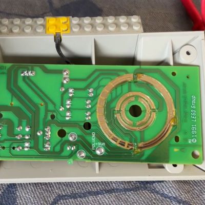
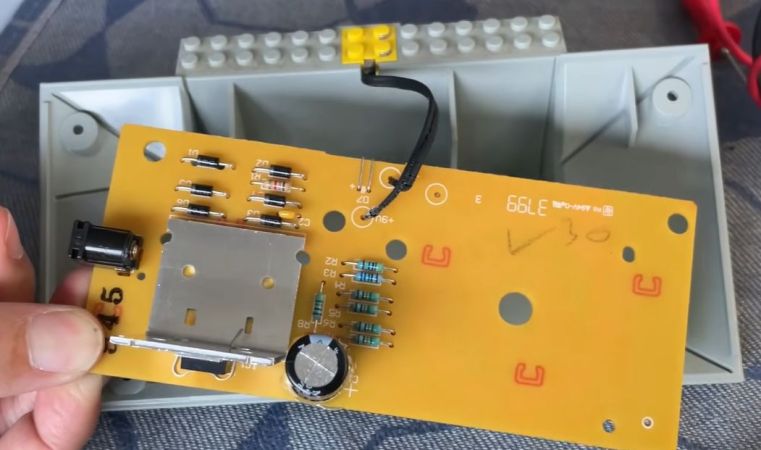
The single PCB inside is quite straightforward, with the 9-12 VAC supply input from an external power adapter, and a variable voltage regulator that sees its target voltage switched by a bank of resistors.

It are these resistors that the big yellow control switches between when you operate it, changing the output voltage and also output polarity you cross the midway point. Effectively this means that there is just one non-passive component on the PCB, in the form of the TO-220 package strapped to the big heatsink.

In this particular unit it was found to be a Fairchild KA317, which is for all intents and purposes here the same as an LM317T. One quick swap later and this controller was back in business like it was 1995.

Compared to the engineering crammed into a modern “smart brick”, things really have come quite a ways in the world of LEGO.

Continue reading “Fixing A 1990s LEGO Electric Train Speed Regulator”
Visualise ESC Problems With LEDs

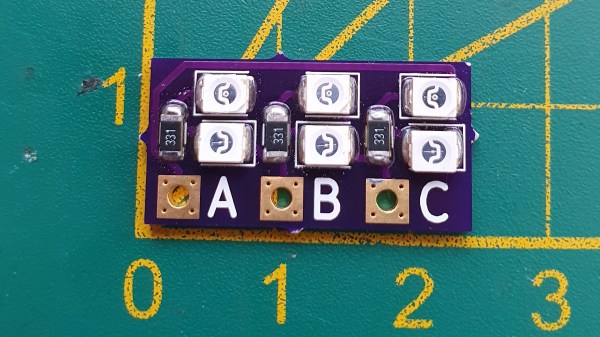
For many in the RC community, blowing up an Electronic Speed Controller (ESC) means one thing: throwing it away and buying another one. However, if you’re regularly pushing the limits or simply hate waste, fixing failed units is an option. To assist in this task, [LouD] built an ingeniously simple ESC tester.

The board is designed to be wired in parallel with a brushless DC motor when hooked up to an ESC. The board packs two LEDs per phase, wired in opposite directions. Thus, current flow in both directions can be visualised on a phase-by-phase basis. If everything is operational, the red and green LEDs on each phase should glow evenly as the throttle is ramped up. However, if there are problems, it will be readily apparent as the blinking becomes erratic or one or more LEDs fails to light at all.

It’s a nifty little device that would prove useful when testing  a pile of possibly-defective units. It’s also a quick way to verify a fix. The project is up on OSHPark should you wish to order your own.

Continue reading “Visualise ESC Problems With LEDs”

Hacked Case Fan Follows The Leader With IR Sensor

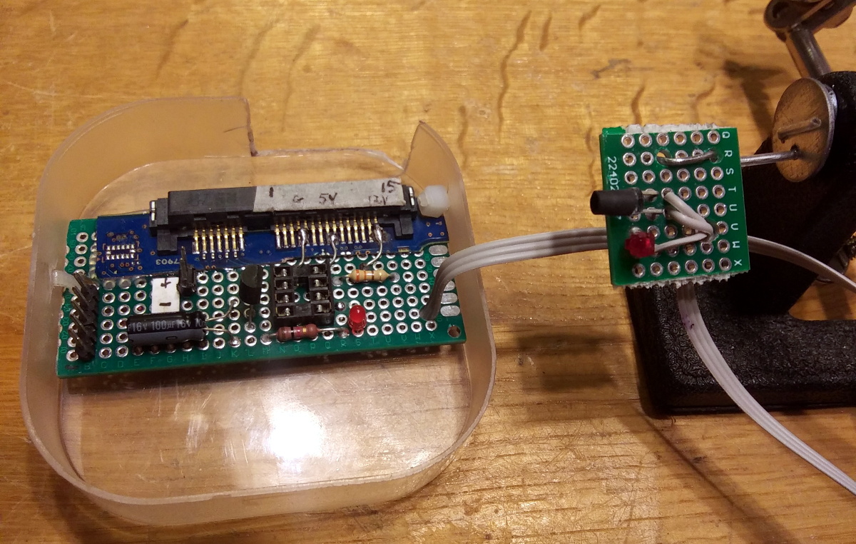
Adding an additional fan to your PC is usually pretty straightforward, but as [Randy Elwin] found, this isn’t always the case with the newer Small Form Factor (SFF) machines. Not only was the standard 80 mm fan too large to fit inside of the case, but there wasn’t even a spot to plug it in. So he had to come up with his own way to power it up and control its speed.

Now if he only needed power, that wouldn’t have been a problem. You could certainly tap into one of the wires coming from the PSU and get 12 V to spin the fan. But that would mean it was running at max speed the whole time; fine in a pinch, but not exactly ideal for a daily driver.

Note the SATA connector pulled from a dead HDD.

To get speed control, [Randy] put together a little circuit using an ATtiny85, an IR LED, and a LTR-306 phototransistor. The optical components are used to detect the GPU fan’s current speed, which itself is controlled based on system temperature. Using the GPU fan RPM as an input, a lookup table on the microcontroller sets an appropriate speed for the 80 mm case fan.

One could argue that it would have been easier to connect a temperature sensor to the ATtiny85, but by synchronizing the case fan to the computer-controlled GPU fan, [Randy] is able to manually control them both from software if necessary. Rather than waiting on the case temperature to rise, he can peg the GPU fan and have the external fan speed up to match when the system is under heavy load.

You may think this is overkill for a simple case fan, but compared to some of the cooling hacks we’ve seen in the past, it’s pretty tame.

A Drop-In Upgrade Module For Cheap Rotary Tools

We’ve all seen them, the rotary tools that look almost, but not quite exactly, like a Dremel. They cost just a fraction of the real thing, and even use the same bits as the official Bosch-owned version. At first glance, they might seem like a perfect solution for the hacker who’s trying to kit out their workshop on a tight budget. There’s only one problem: the similarities between the two are only skin deep.

Recovering components from the original controller

As [Vitaly Puzrin] explains, one of the big problems with these clones are the simplistic electronics which have a tendency to stall out the motor at low RPM. So he’s developed a drop-in replacement speed controller for his particular Dremel clone that solves this problem. While the module design probably won’t work on every clone out there in its current form, he feels confident that with help from the community it could be adapted to other models.

Of course, the first step to replacing the speed controller in your not-a-Dremel is removing the crusty old one. But before you chuck it, you’ll need to recover a few key components. Specifically the potentiometer, filter capacitor, and the motor terminals. You could possibly source the latter components from the parts bin, but the potentiometer is likely going to be designed to match the tool so you’ll want that at least.

The microprocessor controlled upgrade board uses back EMF to detect the motor’s current speed without the need for any additional sensors; important for a retrofit module like this. [Vitaly] says that conceptually this should work on any AC brushed motor, and the source code for the firmware is open if you need to make any tweaks. But hacker beware, the current version of the PCB doesn’t have any AC isolation; you’ll need to take special care if you want to hook it up to your computer’s USB port.

On the other hand, if you’re willing to buy a cheap rotary tool just to crack it open and replace the electronics, you might as well just build your own. If you’re feeling particularly adventurous, you can always abandon the electric motor and spin it up with a tiny turbine. Continue reading “A Drop-In Upgrade Module For Cheap Rotary Tools”

An Open Source ESC For Brushless Motors

For something basic like a brushed DC motor, speed control can be quite simple, and powering up the motor is a simple matter of just applying voltage. Brushless motors are much more demanding in their requirements however, and won’t spin unless driven just right. [Electronoobs] has been exploring the design of a brushless speed controller, and just released version 1.0 of his open-source ESC design.

The basic design is compact, and very similar to many off-the-shelf brushless ESCs in the low power range. There’s a small PCB packing a bank of MOSFETs to handle switching power to the coils of the motor, and a big capacitor to help deal with current spikes. The hacker staple ATMEGA328 is the microcontroller running the show. It’s a sensorless design, which measures the back EMF of the motor in order to determine when to fire the MOSFETs. This keeps things simple for low-torque, low-power applications.

It’s a tidy build, and the latest revision shows a lot of polish compared to the earlier prototypes. If you’re interested to learn more, try building it yourself, or consider building a thrust testing rig for your bench at home. Video after the break.

Continue reading “An Open Source ESC For Brushless Motors”

How Current Shunts Work

Current. Too little of it, and you can’t get where you’re going, too much and your hardware’s on fire. In many projects, it’s desirable to know just how much current is being drawn, and even more desirable to limit it to avoid catastrophic destruction. The humble current shunt is an excellent way to do just that.

Ohm’s Law.

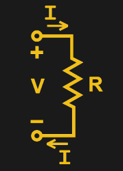
To understand current, it’s important to understand Ohm’s Law, which defines the relationship between current, voltage, and resistance. If we know two out of the three, we can calculate the unknown. This is the underlying principle behind the current shunt. A current flows through a resistor, and the voltage drop across the resistor is measured. If the resistance also is known, the current can be calculated with the equation I=V/R.

This simple fact can be used to great effect. As an example, consider a microcontroller used to control a DC motor with a transistor controlled by a PWM output. A known resistance is placed inline with the motor and, the voltage drop across it measured with the onboard analog-to-digital converter. With a few lines of code, it’s simple for the microcontroller to calculate the current flowing to the motor. Armed with this knowledge, code can be crafted to limit the motor current draw for such purposes as avoiding overheating the motor, or to protect the drive transistors from failure.

In fact, such strategies can be used in a wide variety of applications. In microcontroller projects you can measure as many currents as you have spare ADC channels and time. Whether you’re driving high power LEDs or trying to build protection into a power supply, current shunts are key to doing this.

Continue reading “How Current Shunts Work”

Printed Parts Make DIY Electric Longboard Possible

Appalled by expensive electric longboards, [Conor Patrick] still wanted one, and wanted it now. So — naturally — he converted an existing board into a sprightly electric version at a fraction of the cost.

[Patrick] is using a capable 380KV Propdrive motor, capable of pushing him up to 30mp/h! A waterproof 120A speed controller and 6000mAh, 22.2V LiPo battery slim enough to fit under the board give the motor the needed juice. He ended up buying the cheapest RF receiver and remote combo to control the board, but it fit the all-important “want electric long board now” criterion.

Continue reading “Printed Parts Make DIY Electric Longboard Possible”