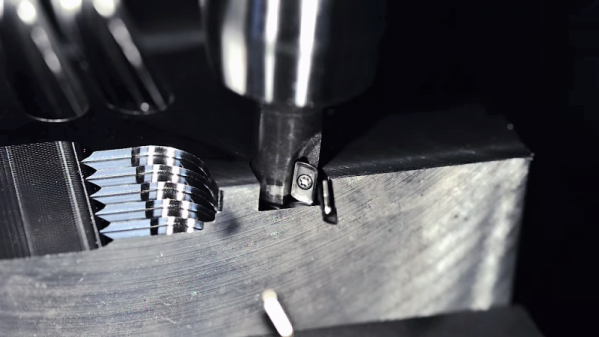
It seems a touch ironic that one of the main consumables in the machining industry is made out of one of the hardest, toughest substances there is. But such is the case for tungsten carbide inserts, the flecks of material that form the business end of most of the tools used to shape metal. And thanks to one of the biggest suppliers of inserts, Sweden’s Sandvik Coromant, we get this fascinating peek at how they’re manufactured.
For anyone into machining, the video below is a must see. For those not in the know, tungsten carbide inserts are the replaceable bits that form the cutting edges of almost every tool used to shape metal. The video shows how powdered tungsten carbide is mixed with other materials and pressed into complex shapes by a metal injection molding process, similar to the one used to make gears that we described recently. The inserts are then sintered in a furnace to bind the metal particles together into a cohesive, strong part. After exhaustive quality inspections, the inserts are ground to their final shape before being shipped. It’s fascinating stuff.
Coincidentally, [John] at NYC CNC just released his own video from his recent jealousy-inducing tour of the Sandvik factory. That video is also well worth watching, especially if you even have a passing interest in automation. The degree to which the plant is automated is staggering – from autonomous forklifts to massive CNC work cells that require no operators, this looks like the very picture of the factory of the future. It rolls some of the Sandvik video in, but the behind-the-scenes stuff is great.
When you think of machine tooling, what comes to mind might be an endmill made of tungsten carbide or a punch and die made of high-speed steel. But surely there’s no room in the machine tool world for 3D-printed plastic tools, especially for the demanding needs of punching parts from sheet metal.
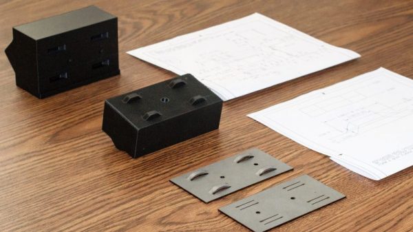
As it turns out, it is possible to make a 3D-printed punch and die set that will stand up to repeated use in a press brake. [Phil Vickery] decided to push the tooling envelope to test this, and came away pleasantly surprised by the results. In fairness, the die he used ended up being more of a composite between the carbon-fiber nylon filament and some embedded metal to reinforce stress points in the die block. It looks like the punch is just plastic, though, and both were printed on a Markforged Mark 2, a printer specifically designed for high-strength parts. The punch and die set were strong enough to form 14-gauge sheet steel in a press brake, which is pretty impressive. The tool wasn’t used to cut the metal; the blanks were precut with a laser before heading to the press. But still, having any 3D-printed tool stand up to metal opens up possibilities for rapid prototyping and short production runs.
No matter what material you make your tooling out of, there’s a lot to know about bending metal. Check out the basics in our guide to the art and science of bending metal.
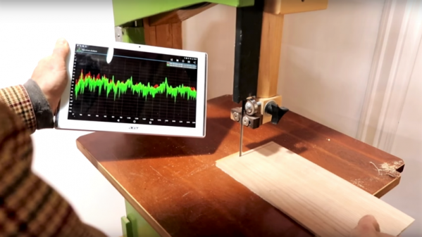
Normally, non-contact tachometers are optically coupled, using photoreceptors to measure light flashing off of a shaft or a tool. But that requires a clear view of the machine, often putting hands far too close to the danger zone. [Matthias Wandel]’s method doesn’t require line of sight because it relies on a cheap spectrum analyzer app to listen to a machine’s sound. The software displays peaks at various frequencies, and with a little analysis and some simple math, the shaft speed of the machine can be determined. [Matthias] explains how to exclude harmonics, where to find power line hum, isolating commutator artifacts, and how to do all the calculations. You’ll need to know a little about your tooling to get the right RPM, and obviously you’ll be limited by the audio frequency response of your phone or tablet. But we think this is a great tip.
[Matthias] is no stranger to shop innovations and putting technology to work in simple but elegant ways. We wonder if spectrum analysis could be used to find harmonics and help with his vibration damping solution for a contractor table saw.
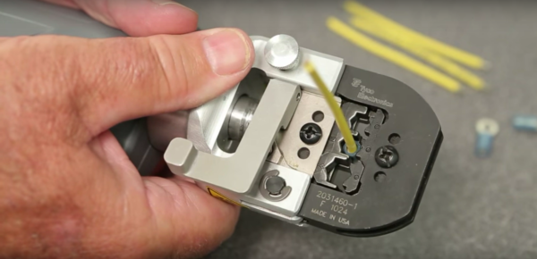
When you move from one-off builds to production scale, perhaps to meet that Kickstarter commitment or to keep your Tindie store stocked, you’re going to need to tool up. Jobs like building wiring harnesses can be tedious and time-consuming, so outsourcing them to this robot wire cutter might be a good idea.
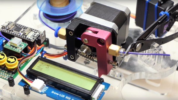
The video below tells the whole tale of this build, which despite the fact that [Maclsk] seems to have put it together quickly from scrap bin parts still looks pretty professional. The business end of the machine is a 3D printer extruder, minus the hot end, of course. A Nano controls the extruder’s stepper to shoot out the right length of wire, as well as the servo that squeezes the snippers. An LCD display and some pushbuttons provide the UI that rounds out the build. Tell it how long and how many, and you’ll be ready to build. We can see how this might be upgraded to strip the wires as well, although getting both ends stripped might be tricky.
Might this component tape-cutting robot from a few weeks back have inspired [Maclsk]’s build? Perhaps, but in any case, both are fun to watch.
I had a friend who was an electronics assembly tech for a big defense contractor. He was a production floor guy who had a chip on his shoulder for the engineers with their fancy book-learnin’ who couldn’t figure out the simplest problems. He claimed that one assembly wasn’t passing QC and a bunch of the guys in ties couldn’t figure it out. He sidled up to assess the situation and delivered his two-word diagnosis: “Bad crimp.” The dodgy connector was re-worked and the assembly passed, much to the chagrin of the guys in the short-sleeved shirts.
Aside from the object lesson in experience sometimes trumping education, I always wondered about that “bad crimp” proclamation. What could go wrong with a crimp to so subtly futz with a circuit that engineers were baffled? How is it that we can rely on such a simple technology to wire up so much of the modern world? What exactly is going on inside a crimped connection anyway?
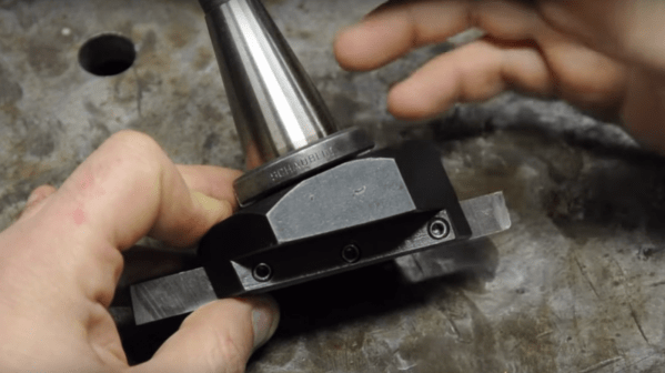
Milling machines can be pretty intimidating beasts to work with, what with the power to cut metal and all. Mount a fly cutter in the mill and it seems like the risk factor goes up exponentially. The off-balance cutting edge whirling around seemingly out of control, the long cutting strokes, the huge chips and the smoke – it can be scary stuff. Don’t worry, though – you’ll feel more in control with a shop-built fly cutter rather than a commercial tool.
Proving once again that the main reason to have a home machine shop is to make tools for the home machine shop, [This Old Tony] takes us through all the details of the build in the three-part video journey after the break. It’s only three parts because his mill released the Magic Smoke during filming – turned out to be a bad contactor coil – and because his legion of adoring fans begged for more information after the build was finished. But they’re short videos, and well worth watching if you want to pick up some neat tips, like how to face large stock at an angle, and how to deal with recovering that angle after the spindle dies mid-cut. The addendum has a lot of great tips on calculating the proper speed for a fly cutter, too, and alternatives to the fly cutter for facing large surfaces, like using a boring head.
[ThisOldTony] does make things other than tooling in his shop, but you’ll have to go to his channel to find them, because we haven’t covered too many of those projects here. We did cover his impressive CNC machine build, though. All [Tony]’s stuff is worth watching – plenty to learn.
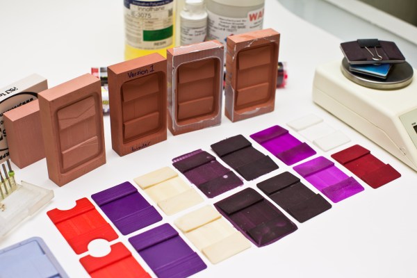
I was in a fit of nerd glee the first time I used tooling board. I’d used MDF for similar purposes before, and I doubt I ever will again. Called Renshape, Precision Board Plus, or that green stuff people on another continent buy; it’s all the same extremely useful, unfortunately expensive, stuff. It’s hard to pin down exactly what tooling board is. Most of the blends are proprietary. It is usually a very dense polyurethane foam, sometimes by itself, sometimes with a fine fiber filler.
What makes tooling board so good is its absolute dimensional stability and its general apathy to normal temperature swings. (It even comes in versions that can go through curing ovens.) It is impervious to humidity. It has good surface finish, and it machines perfectly without wearing down tools.
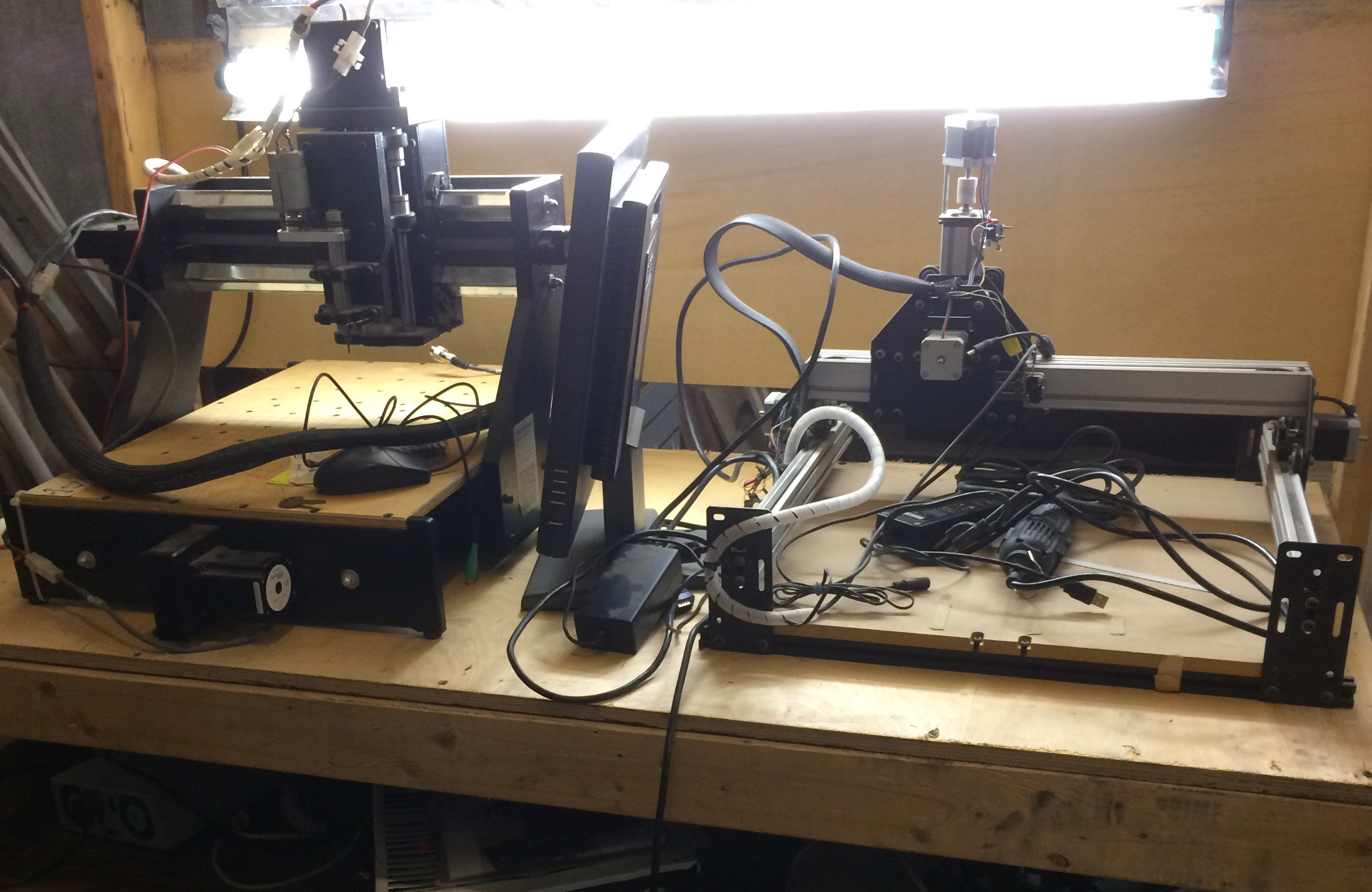
The CNC set-up I coaxed precision molds out of.
This stuff is really tops as far as machining goes. I got super precise molds out of a very basic CNC machine at the LVL1 hackerspace. Renshape cut easily at a high spindle speed, and put practically no load on the machine. Climb and conventional milling were equal load wise with no immediately perceivable difference in finish. In the end I hit the precision range of my cheap digital calipers: +-.005mm, when the temperature is right, the battery is a charged, and the planets align.
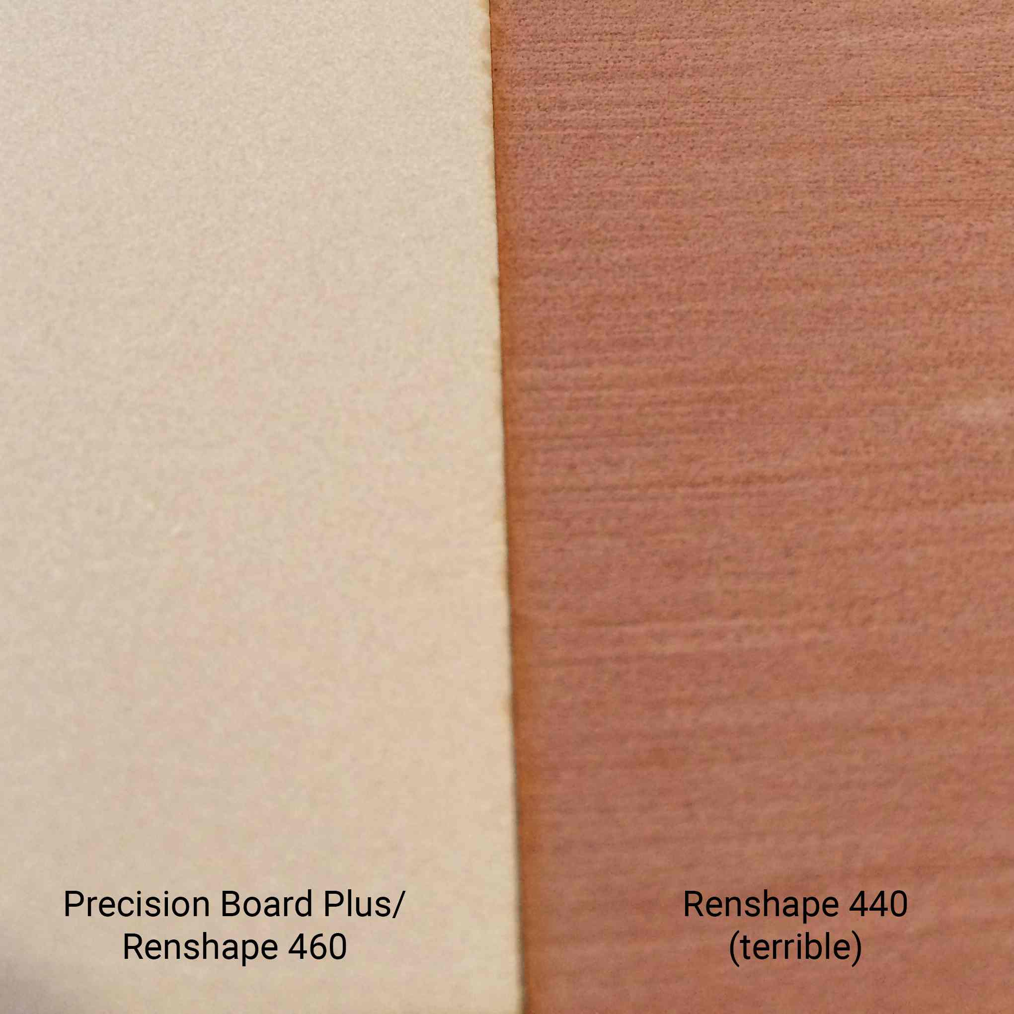
I like to do resin casting when I get serious about a part. If you are making a master mold, there’s nothing better than tooling board. I’ve used both Renshape 460 and Precision Board Plus. Both impart a very light matte pattern, equivalent to a light bead blast on an injection mold. There’s no finishing required, though I mistakenly bought Renshape 440 at first and had to sand it a little to get the finish I wanted.
Tooling board is great for masters in metal casting, and is often used in the industry for just that, especially if quick and accurate prototypes are needed. It’s also tough enough to last through a few rounds of metal stamping in the home shop.
If you are doing lay-up for carbon fiber, fiberglass, or leather, this is also a very good choice. It will be unaffected by the chemicals, heat, and vacuum you may use in the process. It is tough enough hold alignment pins for proper set-up without premature ovaling. It is also a very good choice for vacuum forming.
Tooling board is, unsurprisingly, really good for tooling. It’s a great material for soft-jaws, alignment fixtures, and assembly fixtures, especially if you are doing delicate precision assemblies.
If you’re made of money, tooling board can be used for models, signs and props. It sands, shapes, and files extremely well. It bonds well to a lot of substances. It also takes paint very well with none of the absorption properties of wood or MDF. Most professional model shops will use it. The one big flaw of tooling board is its price — this stuff is expensive. There’s no good DIY version that I’ve scrounged up so far. If you’re making a mold master, a fixture, or anything where you need tooling board’s properties and you are likely to get a few uses out of the board, then it’s probably worth it. Also, be careful of sellers selling plain “Renshape” it is probably going to be the lower grade Renshape 440 and not the more expensive Renshape 460 (or equivalent), where you start to really see the surface finish advantage of the material.
Tooling board is an industrial material. Typically you can call up a supplier and tell them what you’d like to do with it and they will be able to help. If you are making tools for carbon fiber quadcopter frame lay-up, let them know and they’ll have a formulation for that. If you are resin casting, there’s a formulation that gives superior surface finish.
It’s a pretty common material in the industrial scene, but I don’t see it a lot on the hobby scene. This is almost certainly due to its cost, as well as a shortage of small quantity re-sellers. (If someone starts selling assorted sizes on eBay for a reasonable price you have at least one buyer in me.) However, after using it in the niches it is designed for, I really don’t use anything else. I used to hack MDF to fit, but MDF is awful to paint, has no dimensional stability, and dulls tools really fast.
Are you a fan of tooling board? Have a good source? If you have anything to add, let us know in the comments.