Buck Converter Takes 8V To 100V

For those living before the invention of the transistor, the modern world must appear almost magical. Computers are everywhere now and are much more reliable, but there are other less obvious changes as well. Someone from that time would have needed a huge clunky machine like a motor-generator set to convert DC voltages, but we can do it with ease using a few integrated circuits. This one can take a huge range of input voltages to output a constant 5V.

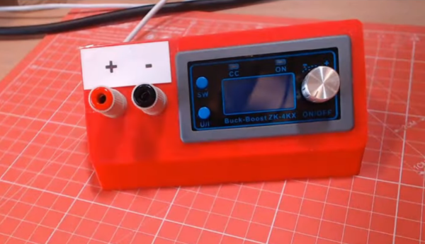
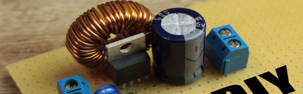
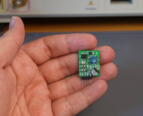
The buck converter was designed by [hesam.moshiri] using a MP9486 chip. While it is possible to use a multipurpose microcontroller like something from Atmel to perform the switching operation needed for DC-DC converters, using a purpose-built chip saves a lot of headache. The circuit was modified a little bit to support the higher input voltage ranges and improve its stability and reliability. The board is assembled in an incredibly tiny package with inputs and outputs readily accessible, so it would be fairly simple to add one into a project rather than designing it from scratch.

Even though buck converters, and other DC converters like boost and the mysterious buck-boost converter, seem like magic even to us, there is some interesting electrical theory going on if you’re willing to dive into the inner workings of high-frequency switching. Take a look at this explanation we featured a while back to see more about how buck converters, the more easily understood among them, work.

Op-Amp Challenge: A Logic-Free BCD

Of digital electronics, a wise man once said that “Every idiot can count to one.” Truer words have rarely been spoken, because at the end of the day, every digital circuit is really just an analog circuit with the interesting bits abstracted away. And to celebrate that way of looking at things, we’re pleased to present this BCD to seven-segment converter that uses no logic chips.

With cheap and easily available chips that perform this exact job, it might seem a little loopy to throw 20 LM324 op-amps at the job. But as [gschmidt958] explains, this is strictly for the challenge, plus it made a nice entry in the recently concluded Op-Amp Challenge contest. His work began in simulation, exploring op-amp versions of the basic logic gates — NAND, AND, OR, and NOT — all of which rely on using the LM324s as comparators. There were real-world curveballs, of course, not least of which was running out of the 10k resistors used for input averaging. Another plot twist was running out of time to order a PCB, which required designing one using MS Paint and etching it at home.

The demo video below shows the circuit at work, taking the BCD output of a 74HC393 counter — clocked by a 555, naturally — and driving a seven-segment LED.  It’s honestly a lot of work for such a simple task, but there’s something satisfying about the whole project. We think [Widlar] would be proud.

Continue reading “Op-Amp Challenge: A Logic-Free BCD”

Bench Supplies Get Smaller Thanks To USB-C

Bench power supplies are an indispensable tool when prototyping electronics. Being able to set custom voltages and having some sort of current limiting feature are key to making sure that the smoke stays inside all of the parts. Buying a modern bench supply might be a little too expensive though, and converting an ATX power supply can be janky and unreliable. Thanks to the miracle of USB-C, though, you can build your own fully-featured benchtop power supply like [Brian] did without taking up hardly any space, and for only around $12.

USB-C can be used to deliver up to 100W but is limited to a few set voltage levels. For voltages that USB-C doesn’t support, [Brian] turns to an inexpensive ZK-4KX buck-boost DC-DC converter that allows for millivolt-level precision for his supply’s output. Another key aspect of using USB-C is making sure that your power supply can correctly negotiate for the amount of power that it needs. There’s an electronic handshake that goes on over the USB connection, and without it there’s not a useful amount of power that can be delivered. This build includes a small chip for performing this negotiation as well.

With all the electronics taken care of, [Brian] houses all of this in a 3D-printed enclosure complete with a set of banana plugs. While it may not be able to provide the wattage of a modern production unit, for most smaller use cases this would work perfectly. If you already have an ATX supply around, though, you can modify [Brian]’s build using that as the supply and case too.

Continue reading “Bench Supplies Get Smaller Thanks To USB-C”

Modern Mice On Old Computers

Getting retro hardware up and running again is sometimes a feat, and the amount of effort needed tends to go up exponentially with increased hardware age. Getting an IDE hard drive running again is one thing, but things like peripherals on truly “retro” computers like Commodores and Amigas is another beast altogether if you even have a 30-year-old mouse still lying around. That’s why adapters like Project mouSTer are here to help you connect modern USB hardware to truly ancient computers.

This piece of equipment was built for the Atari ST (hence the name), a 8-bit  computer from the mid-80s. It mates a DB9 plug with USB via a small microcontroller which does the translating. The firmware can be flashed over the USB connection so there’s planned support for other machines of this vintage. The chip supports all the features the original mouse did, too, including PS4 pad support and support for joysticks, and comes in an impressively tiny package once assembled which blends in seamlessly.

The project is a great step to getting retro computers working again, even if you can’t find exact OEM replacements anymore. That’s a common problem, and we’ve seen this solved in other ways for other old Ataris. It’s not uncommon to put modern power supplies in retro computers, either, as long as they power up and work after everything’s wired together.

RTFM: ADCs And DACs

It’s tough to find a project these days that doesn’t use an analog-to-digital converter (ADC) or digital-to-analog converter (DAC) for something. Whether these converters come as built-in peripherals on a microcontroller, or as separate devices connected over SPI, I2C, or parallel buses, all these converters share some common attributes, and knowing how to read the specs on them can save you a lot of headaches when it comes to getting things working properly.

There are some key things to know about these devices, and the first time you try to navigate a datasheet on one, you may find yourself a bit confused. Let’s take a deep dive into the static (DC) properties of these converters — the AC performance is complex enough to warrant its own follow-up article.

Continue reading “RTFM: ADCs And DACs”

HDMI Extender Reverse Engineered

[danman] has been playing around with various HDMI video streaming options, and he’s hit on a great low-cost solution. A $40 “HDMI extender” turns out to actually be an HDMI-to-RTP converter under the hood.

He’d done work previously on a similar extender that turned out to use a quirky method to send the video, which he naturally reversed and made to do his bidding. But non-standard formats are a pain. So when he was given a newer version of the same device, and started peeking into the packets with Wireshark, he was pleasantly surprised to find that the output was just MPEG-encoded video over RTP. No hacking necessary.

Until now, streaming video over an IP network from an arbitrary HDMI output has been tricky, [danman] has been more than a little obsessed with getting it working on the cheap. In addition to the previous version of this extender, he also managed to get a stream out of a rooted Android set-top box. That costs a bit more, but can also record at the same time, should you need to.

None of this solves the HDMI HDCP encryption problem, though. You’re on your own for that one.

(Those of you Wireshark wizards out there will note that we just swiped the headline image from the previous version of the project. There were no good images for this one. Sorry about that.)

How Does A Buck Converter Work Anyway?

[Great Scott] should win an award for quickest explanation of a buck converter. Clocking in at five and a half minutes, the video clearly shows the operating principles behind the device.

It starts off with the question, what should you do if you want to drop a voltage? Many of us know that we can dim and brighten an LED using the PWM on an Arduino, but a closer inspection with an oscilloscope still shows 5V peaks that would be dangerous to a 3.3V circuit. He then adds an inductor and diode, this keeps the current from dropping too fast, but the PWM just isn’t switching fast enough to keep the coil energized.

A small modification to the Arduino’s code, and the PWM frequency is now in the kHz range. The voltage looks pretty good on the oscilloscope, but a filter cap gets it to look nice and smooth. Lastly, he shows how when the load changes the voltage out looks different. To fix this a voltage divider feeds back the information to the Arduino, letting it change the PWM duty to match the load.

In the last minute of the video he shows how to hook up off-the-shelf switching regulators, whose support components are now completely demystified as the basic principles are understood. Video after the break.

Continue reading “How Does A Buck Converter Work Anyway?”