If you need to send data from sensors, there are plenty of options, including a bewildering selection of wireless methods. Trouble is, most of those protocols require a substantial stack of technology to make them work, and things aren’t much easier with wired sensors either. It doesn’t have to be that complicated, though, as this simple two-wire power-and-data interface demonstrates.
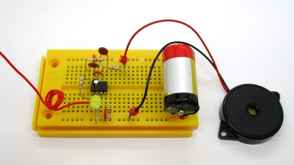
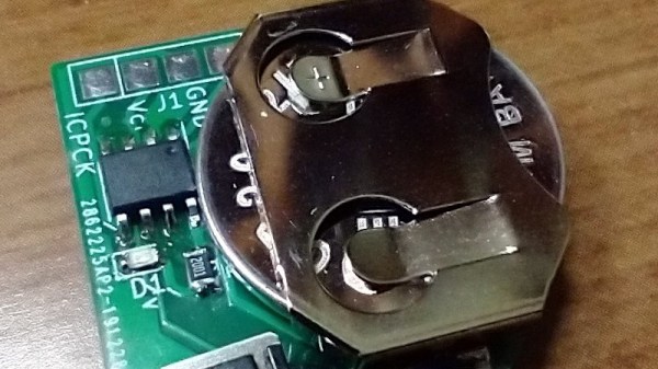
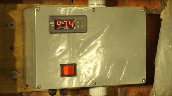
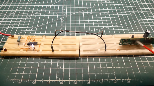
As with all things electronic, there are tradeoffs, which [0033mer] addresses in some detail in the video below. The basic setup for his use case is a PIC-based sensor — temperature, for this demo — that would be mounted in some remote location. The microcontroller needs to be powered, of course, and also needs to send a signal back to a central point to indicate whether the monitored location is within temperature specs. Both needs are accommodated by a single pair of wires and a tiny bit of additional circuitry. On one end of the twisted pair is a power supply and decoder circuit, which sends 9 volts up the line to power the PIC sensor. The decoder is based on a CD4538 dual monostable multivibrator, set up for an “on” time of one second. A trigger input is connected to the power side of the twisted pair going to the sensor, where a transistor connected to one of the PIC’s GPIO pins is set up to short the twisted pair together every half-second. Power to the PIC is maintained by a big electrolytic and a diode, to prevent back-feeding the controller. The steady 0.5-Hz stream of pulses from the sensor keeps resetting the timer on the control side. Once that stream stops, either through code or by an open or short condition on the twisted pair, the controller triggers an output to go high.
It’s a pretty clever system with very simple and flexible circuitry. [0033mer] says he’s used this over twisted-pair wires a couple of hundred feet long, which is pretty impressive. It’s limited to one bit of bandwidth, of course, but that might just be enough for the job. If it’s not, you might want to check out our primer on current-loop sensors, which are better suited for analog sensors but still share some of the fault-detection features.
Continue reading “Simple CMOS Circuit Allows Power And Data Over Twisted-Pair Wiring”