A Switching Power Supply, 1940s-Style

“They don’t build ’em like they used to.” There’s plenty of truth to that old saw, especially when a switch-mode power supply from the 1940s still works with its original parts. But when said power supply is about the size of a smallish toddler and twice as heavy, building them like the old days isn’t everything it’s cracked up to be.

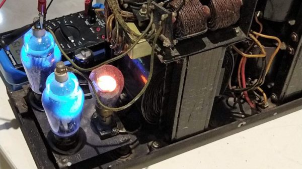
The power supply that [Ken Shirriff] dives into comes from an ongoing restoration of a vintage teletype we covered recently. In that post we noted the “mysterious blue glow” of the tubes in the power supply, which [Ken] decided to look into further. The tubes are Thyratrons, which can’t really be classified as vacuum tubes since they’re filled with various gasses. Thyratrons are tubes that use ionized gas – mercury vapor in this case – to conduct large currents. In this circuit, the Thyratrons are used as half-wave rectifiers that can be rapidly switched on and off by a feedback circuit. That keeps the output voltage fixed at the nominal 140V DC required by the teletype, with a surprisingly small amount of ripple. The video below is from a series on the entire restoration; this one is cued to where the power supply is powered up for the first time. It’s interesting to see the Thyratrons being switched at about 120 Hz when the supply is under load.

Cheers to [Ken] and his retrocomputing colleagues for keeping the old iron running. Whether the target of his ministrations is a 1974 scientific calculator or core memory from an IBM 1401, we always enjoy watching him work.

Continue reading “A Switching Power Supply, 1940s-Style”

The How And Why Of Tungsten Carbide Inserts, And A Factory Tour

It seems a touch ironic that one of the main consumables in the machining industry is made out of one of the hardest, toughest substances there is. But such is the case for tungsten carbide inserts, the flecks of material that form the business end of most of the tools used to shape metal. And thanks to one of the biggest suppliers of inserts, Sweden’s Sandvik Coromant, we get this fascinating peek at how they’re manufactured.

For anyone into machining, the video below is a must see. For those not in the know, tungsten carbide inserts are the replaceable bits that form the cutting edges of almost every tool used to shape metal. The video shows how powdered tungsten carbide is mixed with other materials and pressed into complex shapes by a metal injection molding process, similar to the one used to make gears that we described recently. The inserts are then sintered in a furnace to bind the metal particles together into a cohesive, strong part. After exhaustive quality inspections, the inserts are ground to their final shape before being shipped. It’s fascinating stuff.

Coincidentally, [John] at NYC CNC just released his own video from his recent jealousy-inducing tour of the Sandvik factory. That video is also well worth watching, especially if you even have a passing interest in automation. The degree to which the plant is automated is staggering – from autonomous forklifts to massive CNC work cells that require no operators, this looks like the very picture of the factory of the future. It rolls some of the Sandvik video in, but the behind-the-scenes stuff is great.

Continue reading “The How And Why Of Tungsten Carbide Inserts, And A Factory Tour”

Save Fingers, Save Lives With A No-Voltage Release For The Shop

Imagine the scenario: you’re spending some quality time in the shop with your daughter, teaching her the basics while trying to get some actual work done. You’re ripping some stock on your cheap table saw when your padiwan accidentally hooks the power cord with her foot and pulls out the plug. You have a brief chat about shop safety and ask her to plug it back in. She stoops to pick up the cord and plugs it back in while her hand is on the table! Before you can stop the unfolding tragedy, the saw roars to life, scaring the hell out of everyone but thankfully doing no damage.

If that seems strangely specific it’s because it really happened, and my daughter was scared out of the shop for months by it. I’ll leave it to your imagination what was scared out of me by the event. Had I only known about no-voltage release switches, or NVRs, I might have been able to avoid that near-tragedy. [Gosforth Handyman] has a video explaining NVRs that’s worth watching by anyone who plugs in anything that can spin, cut, slice, dice, and potentially mutilate. NVRs, sometimes also called magnetic contactors, do exactly what the name implies: they switch a supply current on and off, but automatically switch to an open condition if the supply voltage fails.

Big power tools like table saws and mills should have them built in to prevent a dangerous restart condition if the supply drops, but little tools like routers and drills can still do a lot of damage if they power back up while switched on. [Gosforth] built a fail-safe power strip for his shop from a commercial NVR, and I’d say it’s a great idea that’s worth considering. Amazon has a variety of NVRs that don’t cost much, at least compared to the cost of losing a hand.

True, an NVR power strip wouldn’t have helped me with that cheap table saw of yore, but it’s still a good idea to put some NVR circuits in your shop. Trust me, it only takes a second’s inattention to turn a fun day in the shop into a well-deserved dressing down by an angry mother. Or worse.

Continue reading “Save Fingers, Save Lives With A No-Voltage Release For The Shop”

Fail Of The Week: How Not To Design An RF Signal Generator

We usually reserve the honor of Fail of the Week for one of us – someone laboring at the bench who just couldn’t get it together, or perhaps someone who came perilously close to winning a Darwin Award. We generally don’t highlight commercial products in FotW, but in the case of this substandard RF signal generator, we’ll make an exception.

We suppose the fail-badge could be pinned on [electronupdate] for this one in a way; after all, he did shell out $200 for the RF Explorer signal generator, which touts coverage from 24 MHz to 6 GHz. But in true lemons-to-lemonade fashion, the video below he provides us with a thorough analysis of the unit’s performance and a teardown of the unit.

The first step is a look at the signal with a spectrum analyzer, which was not encouraging. Were the unit generating a pure sine wave as it should, we wouldn’t see the forest of spikes indicating harmonics across the band. The oscilloscope isn’t much better; the waveform is closer to a square wave than a sine. Under the hood, he found a PIC microcontroller and a MAX2870 frequency synthesizer, but a conspicuous absence of any RF filtering components, which explains how the output got so crusty. Granted, $200 is not a lot to spend compared to what a lab-grade signal generator with such a wide frequency range would cost. And sure, external filters could help. But for $200, it seems reasonable to expect at least some filtering.

We applaud [electronupdate] for taking one for the team here and providing some valuable tips on RF design dos and don’ts. We’re used to seeing him do teardowns of components, like this peek inside surface-mount inductors, but we like thoughtful reviews like this too.

Continue reading “Fail Of The Week: How Not To Design An RF Signal Generator”

Ask Hackaday: Managing Inspiration

For most of us, hacking is a hobby, something to pass a few idle hours and satisfy our need to create. Precious few of us get to live the dream of being paid to tinker; most of us need some kind of day job to pay the bills and support our hacking habits. This necessarily creates an essential conflict, rooted in the fact that we all only have 24 hours to spread around every day: I need to spend my time working so I can afford to hack, but the time I spend working to earn money eats away at my hacking time. That’s some catch, that Catch-22.

From that primary conflict emerges another one. Hacking is a hugely creative process, and while the artist or the author might not see it that way, it’s true nonetheless. Unless we’re straight-up copying someone else’s work, either because they’ve already solved the same problem we’re working on and we just need to get it done, or perhaps we’re just learning a new skill and want to stick to the script, chances are pretty good that we’re hitting the creative juices hard when we build something new. And that requires something perhaps even more limiting than time: inspiration. How you manage inspiration in large part dictates how productive you are in your creative pursuits.

Continue reading “Ask Hackaday: Managing Inspiration”

Chemistry And Lasers Turn Any Plastic Surface Into A PCB

On the face of it, PCB production seems to pretty much have been reduced to practice. Hobbyists have been etching their own boards forever, and the custom PCB fabrication market is rich with vendors whose capabilities span the gamut from dead simple one-side through-hole boards to the finest pitch multilayer SMD boards imaginable.

So why on Earth would we need yet another way to make PCBs? Because as [Ben Krasnow] points out, the ability to turn almost any plastic surface into a PCB can be really handy, and is not necessarily something the fab houses handle right now. The video below shows how [Ben] came up with his method, which went down a non-obvious path that was part chemistry experiment, part materials science. The basic idea is to use electroless copper plating, a method of depositing copper onto a substrate without using electrolysis.

This allows non-conductive substrates — [Ben] used small parts printed with a Formlabs SLA printer — to be plated with enough copper to form solderable traces. The chemistry involved in this is not trivial; there are catalysts and surfactants and saturated solutions of copper sulfate to manage. And even once he dialed that in, he had to figure out how to make traces and vias with a laser cutter. It was eventually successful, but it took a lot of work. Check out the video below to see how he got there, and where he plans to go next.

You’ve got to hand it to [Ben]; when he decides to explore something, he goes all in. We appreciate his dedication, whether he’s using candles to explore magnetohydrodynamics or making plasma with a high-speed jet of water.

Continue reading “Chemistry And Lasers Turn Any Plastic Surface Into A PCB”

Air Wrench Becomes A Milling Machine Power Drawbar

We sometimes wonder if designers ever actually use their own products, or even put them through some sort of human-factors testing before putting them on the market. Consider the mechanism that secures toolholders to the spindle of a milling machine: the drawbar. Some mills require you to lock the spindle with a spanner wrench, loosen the drawbar with another wrench, and catch the released collet and tool with – what exactly?

Unwilling to have the surgical modifications that would qualify him for the Galactic Presidency, [Physics Anonymous] chose instead to modify his mill with a power drawbar. The parts are cheap and easily available, with the power coming from a small butterfly-style pneumatic wrench. The drawbar on his mill has a nearly 3/8″ square drive – we’d guess it’s really 10 mm – which almost matches up with the 3/8″ drive on the air wrench, so he whipped up a female-to-female adapter from a couple of socket adapters. The wrench mounts to a cover above the drawbar in a 3D-printed holster. Pay close attention to the video below where he goes through the Fusion 360 design; we were intrigued by the way he imported three orthogonal photos on the wrench to design the holster around. That’s a tip to file away for a rainy day.

This is a great modification to a low-cost milling machine. If you’re in the process of buying machine tools, you should really check out our handy buyer’s guides for both milling machines and lathes. It’ll let you know what features to look out for, and which you’ll have to add later.

Continue reading “Air Wrench Becomes A Milling Machine Power Drawbar”