Transistor Logic Clock Gets Stacked Up

A couple years back we covered a very impressive transistor logic clock which was laid out so an observer could watch all of the counters doing their thing, complete with gratuitous blinkenlights. It had 777 transistors on 41 perfboards, and exactly zero crystals: the clock signal was extracted from the mains frequency of 50 Hz. It was obviously a labor of love and certainly looked impressive, but it wasn’t exactly the most practical timepiece we’d ever seen.

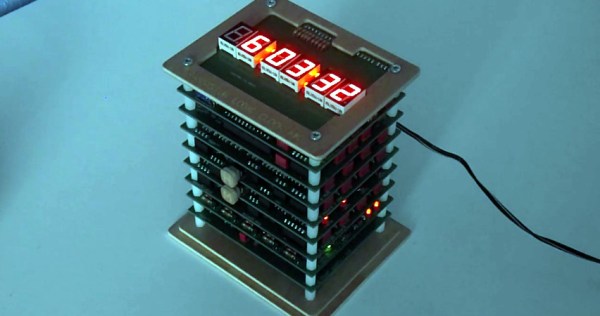
Creator [B Brett] recently wrote in to share news that the second version of his transistor logic clock has been completed, and we can confidently say it’s a triumph. He’s dropped the 41 perfboards in favor of 9 professionally fabricated PCBs, which this time around are stacked vertically to make it a bit more desktop friendly. The end goal of a transistor logic clock that you can take apart to study is the same, but this “MkII” as he calls it is a far more refined version of the concept.

In addition to using fewer boards, the new MkII design cuts the logic down to only 283 transistors. This is thanks in part to the fact that he allowed himself the luxury of including an oscillator this time. The clock uses a standard watch crystal at 32.768 KHz, the output of which is converted into a square wave through a Schmitt trigger. This is then fed into a divider higher up the stack which uses flip flops to produce 1Hz and 2Hz signals for use throughout the rest of the clock.

In addition to the original version of this project, we’ve also seen a beautiful single-board wall mounted version, and even a “dead bug” style one built from scraps.

Continue reading “Transistor Logic Clock Gets Stacked Up”

ZPB30A1 Electronic Load Gets An Open Firmware

Importing cheap equipment and test gear is something of a mixed blessing. It allows you to outfit your lab without emptying your bank account, but on the other hand there’s usually a reason it’s cheap. Of course, the retail price of a piece of hardware shouldn’t be the metric by which we measure its quality, but there’s got to be a few corners cut someplace when they are selling this stuff for a fraction of what the name brands are charging.

A perfect example is the ZHIYU ZPB30A1 electronic load, available from various online importers for about $30 USD. While the price is right for an adjustable load that can handle up to 110 W, it’s got some pretty glaring shortcomings. In an effort to address at least some of those issues, [Luca Zimmermann] has been working on an open source replacement firmware for the load’s STM8S microcontroller.

[Luca] quickly discovered that the device’s STM8S005K6 chip is write protected, so unfortunately you can’t just flash a new firmware to it. If you want to unlock additional features, you need to perform a brain transplant. Luckily these chips are quite cheap, and you can probably add a couple of them to your cart when you order he ZPB30A1.

With the new GPLv3 licensed firmware installed, the device gains constant power and resistances modes (stock firmware can only do constant current), serial logging, and support for adjusting the value of the shunt resistor. There’s even a basic menu system to shuffle through the new modes. There’s still a couple features that haven’t been implemented, such as automatic shutdown, but it’s already a considerable upgrade from the stock software. Now we just need some details on the slick custom enclosure that [Luca] has put his upgraded ZPB30A1 into.

If this looks too easy, you can always go the DIY Arduino route for your load testing needs, or build a monster than can sink up to 1 kW.

[Thanks to Benik3 for the tip.]

3D Printed RC Jet Boat Gets Up To Speed

In one of those weird twists of fate, there’s currently a very high chance that anyone who owns a 3D printer has made a boat with it. In fact, they’ve probably printed several of them, so many that they might even have a shelf filled with little boats in different colors and sizes. That’s because it’s a popular benchmark to make sure the printer is well calibrated. But if you’re going to spend hours printing out a boat, why not print one that’s got some punch?

This 3D printable jet boat designed by [Jotham B] probably isn’t a great print to check your desktop machine’s calibration on, in fact you’re going to want to make sure you’ve got everything dialed in before taking on this challenge. If the classic “Benchy” is the beginners boat, then this is certainly for the 3D printing veterans. But if you’ve got the skills to pull it off, and some RC gear laying around to outfit it with, this could be a great project to end your summer on.

Unless you’ve got an exceptionally tall printer, the 460mm long hull will need to be printed in several pieces and then grafted back together. You could potentially use glue, but something a bit more robust like welding the parts together with a soldering iron is a better bet to make sure your printed boat doesn’t do its best Titanic reenactment out on the lake.

[Jotham] recommends printing the impeller at 0.15mm layer height, as you’ll want all the detail you can muster to provide a smooth surface. You’ll also need to use supports, so expect to spend a fair bit of time cleaning it up post-print. The rest of the model can be printed at 0.3mm, which is going to save a lot of time on the hull. All told, it will take about half a roll of filament to print all the parts for the boat (assuming no mistakes), which puts the pre-electronics cost at around $10 USD.

Speaking of electronics, you’ll need a RC receiver, a servo for steering, an electronic speed controller (ESC), and a suitable motor. [Jotham] used a 3674 brushless motor with a 120A water-cooled ESC, but notes that the setup is way overpowered. In the video after the break you can see the boat spends as much time airborne as it does in the water, which might look cool, but isn’t exactly efficient.

If you want to round out your 3D PLA fleet, we’ve also seen a printed FPV lifeboat as well as a hydrofoil that “flies” through the water.

[Thanks to Aidan for the tip.]

Continue reading “3D Printed RC Jet Boat Gets Up To Speed”

A Custom Built FPV Monitor To Keep The Fans Happy

If you’re going to be flying around a FPV-capable aircraft, be it a quadcopter or a fixed-wing plane, you shouldn’t be surprised if bystanders want to take a turn wearing your googles. Of course we hope that you’re good enough flying line of sight that you don’t need to be wearing the googles to stay airborne, but it does make it harder to pull off the sort of tricks and maneuvers that your audience wants to see. So if you want to put on a good show, the audience really needs their own display.

Unfortunately, as avid FPV flier [Michael Delaney] discovered, even the “cheap” ones will run you at least $100 USD. So he did what any self-respecting hacker would do, he set out to build his own. Using a collection of off the shelf components he was able to build a very impressive monitor that lets the viewer see through the eyes of his quadcopter at less than half the cost of commercially available offerings. Though even if he hadn’t manged to beat the cost of a turn-key monitor, we think it would have been more than worth it for this piece of highly customized gear.

At the heart of the monitor is a Boscam RX5808 5.8 GHz receiver, which is controlled by an Arduino Pro Mini. The video output from the receiver is sent to a 4.2″ TFT screen intended for the Raspberry Pi, and on the backside of the laser-cut wooden enclosure there’s a 128 x 64 I2C OLED to display the currently selected channel and diagnostic information.

An especially nice touch for this project is the custom PCB used to tie all the components together. [Michael] could have taken the easy route and sent the design out for fabrication, but instead went with the traditional method of etching his own board in acid. Though he did modernize the process a bit by using a laser and pre-sensitized copper clad board, a method that seems to be gaining in popularity as laser engravers become a more common component of the hacker’s arsenal.

We’ve previously covered using the RX5808 and Arduino combo to create a spectrum analyzer, in case you want to do more than just watch your friends do powerloops.

LED “Candle” Gets The 555 Treatment

Regular readers may recall we recently covered a neat Arduino trick that allowed you to “blow out” an LED as if it was a candle. The idea was that the LED itself could be used as a rudimentary temperature sensor, and the Arduino code would turn the LED on and off when a change was detected in its forward voltage drop. You need to oversample the Arduino’s ADC to detect the few millivolt change reliably, but overall it’s pretty simple once you understand the principle.

But [Andrzej Laczewski], like many of our beloved readers, feels the Arduino and other microcontrollers can be a crutch if used exclusively. So he set out to replicate this hack with that most cherished of ICs, the 555 timer. In the video after the break, he demonstrates his “old-school” LED candle for anyone who thinks the only way to control an LED is with digitalWrite.

Not to say it’s easy to replicate the original Arduino project with a 555, or that it’s even practical. [Andrzej] simply wanted to show it was possible, which is something we always respect around these parts. He goes into great detail on how he developed and tested the circuit, even including oscilloscope screenshots showing how the different components work together in real-time. But the short version is that a MOSFET is used to turn the LED on and off, a comparator detects change in the LED’s voltage drop, and the 555 is used to control how long the LED stays off for.

Ever the traditionalist, [Andrzej] wrapped up this build by etching his own PCB using a variation of the classic laser toner transfer method. If this all looks a bit too much like Black Magic to you, there’s no shame in sticking with the Arduino version. At 1/20th of the parts count, and with no calibration required, who’s to say which version is “simpler”.

Continue reading “LED “Candle” Gets The 555 Treatment”

GPS Overlays Give Real Life Racing A Video Game Feel

Racing is certainly exciting for the person rocketing around the track fast enough to get the speedometer into the triple digits, and tends to be a decent thrill for the spectators if they’ve got good seats. But if you’re just watching raw race videos on YouTube from the comfort of your office chair it can be a bit difficult to appreciate. There’s a lack of context for the viewer, and it can be hard to get the same sense of speed and position that you’d have if you saw the event first hand.

In an effort to give his father’s racing videos a bit more punch, [DusteD] came up with a clever way of adding video game style overlays to the recordings. The system provides real-time speed, lap times, and even a miniature representation of the track complete with a marker to show where the action is taking place. The end result is that recordings of Dad’s exploits on the track could pass as gameplay footage from Gran Turismo (we know GT doesn’t have motorcycles, but you get the idea).

The first part of the system is the tracker itself, which consists of a GPS receiver, an Arduino Pro Micro, and an SD card module. [DusteD] powers the device with two 18650 cells in parallel, and a DC-DC boost converter to step it up to 5V. Everything is contained in a 3D printed enclosure that he designed in OpenSCAD, with the only external elements being a toggle switch, a momentary switch, and most critically, a set of LEDs.

These LEDs play into the second part of the system, the software. The blinking LEDs are positioned so they’ll get picked up by the camera, which is then used to help synchronize the data stored on the SD card with the video. [DusteD] came up with some software that will take the speed and position information from the card, and turn it into PNG files with transparent backgrounds. These are then placed on top of the video with the help of FFmpeg. It takes a little adjustment to get everything lined up properly, but as the video after the break shows the end result is very impressive.

This build reminds us of the Raspberry Pi powered GPS helmet camera we featured a few years back, and it’s interesting to see how the two projects achieved what’s essentially the same goal in different ways.

Continue reading “GPS Overlays Give Real Life Racing A Video Game Feel”

Printed It: Logitech C270 Conversion

One of the most practical applications for a home 3D printer is the ability to produce replacement parts; why wait a week for somebody to ship you a little plastic widget when you’ve got a machine that can manufacture a facsimile of it in a couple of hours? But what if your skills and passion for the smell of melting PLA push you even farther? You might move on from printing replacement parts to designing and building whole new devices and assemblies. Arguably this could be considered “peak” 3D printing: using a printer to create new devices which would otherwise be difficult or impractical for an individual to manufacture by more traditional means.

A perfect example is this fantastic total conversion for the Logitech C270 webcam designed by [Luc Eeckelaert]. Officially he calls it a “tripod”, and perhaps that’s how the design started, but the final product is clearly much more than that. It puts the normally monitor-mounted Logitech camera onto an articulated arm, greatly improving the device’s usability. The conversion even includes the ability to manually adjust the focus, a feature the original hardware doesn’t have. It turns the affordable and widely available Logitech C270 into an excellent camera to have on the workbench for documenting projects, or pointing at the bed of your 3D printer.

Continue reading “Printed It: Logitech C270 Conversion”