Software Defined Radio Gets Physical Control

Software Defined Radio (SDR) is a great technology, but there’s something so satisfying about spinning a physical knob to cruise the airwaves. Wanting to restore that tactile experience, [Tysonpower] purchased a cheap USB volume knob and set out to get it working with his software. Unfortunately, getting it up and running took a lot more work than you’re probably expecting.
Programming the knob’s STM32

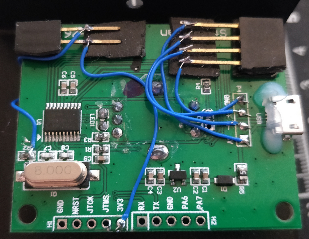
After verifying that the knob worked for volume control on his computer, [Tysonpower] decided to try and pull the firmware from the device’s STM32 microcontroller. Unfortunately, this is where things got tricky. It turned out the chip had Code Protection enabled, so when it was wired up to a programmer and put into DFU mode, the firmware got wiped. Oops.

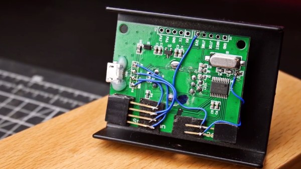
That left [Tysonpower] with no choice but to write a new firmware from scratch, which naturally required reverse engineering the device’s hardware. Step one was reading up on STM32 development and getting the toolchain working, which paved the way to getting the knob’s LED to blink. A couple more hours worth of work and some multimeter poking later, and he was able to read the knob’s movement. He describes getting USB HID working as a nightmare due to lack of documentation, but eventually he got that sorted out as well.

The end result is a firmware allows the volume knob to mimic a mouse scroll wheel, which can be used for tuning in many SDR packages. But we think the real success story is the experience [Tysonpower] gained with reverse engineering and working with the STM32 platform. After all, sometimes the journey is just as important as the end result. Continue reading “Software Defined Radio Gets Physical Control”

An Arduino And An Enigma All Rolled Into One

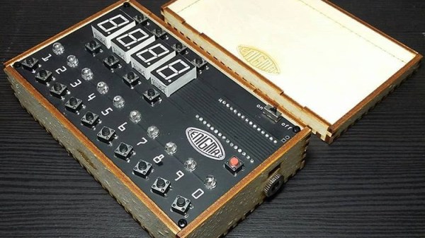
This hacker has been wanting to design an Enigma machine simulator for a while, but didn’t take the leap until they realized there was a compact Arduino with a surplus of I/O.

The logs go through all sort of variations on the machine. Everything from a plug board variation similar to the original to a 16 segment LED tester are covered. In one of the posts you can even see it decode a real U-Boat message. 

The earlier revisions are housed in very attractive laser cut cases but the latest designs employ an even more elegant casing solution. The simulator uses 16 segment displays and momentary push buttons for the keys. At its core is a 2560 Pro mini. The write-up contains a lot of detail about the code behind the Enigma and is interesting to read.  Interestingly, the PCB was designed in Fritzing, the EDA software many love to hate.

We love the craftsmanship and attention going into this project and can see it turning into a very appealing kit as it goes through its design cycles.

Supercon SMD Challenge Gets 3D Printed Probes: Build Your Own

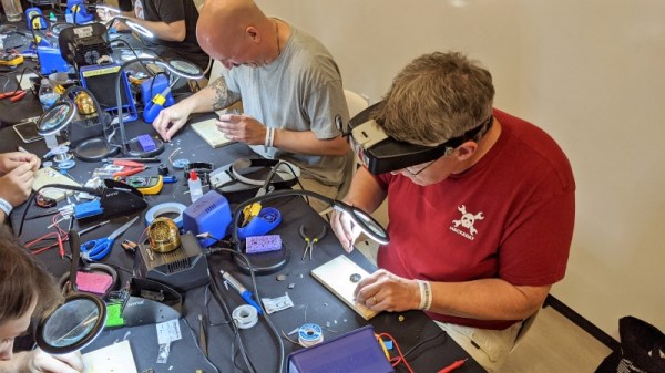
This year was the second SMD challenge at Supercon, so it stands to reason we probably learned a few things from last year. If you aren’t familiar with the challenge, you are served some pretty conventional tools and have to solder a board with LEDs getting progressively smaller until you get to 0201 components. Those are challenging even with proper tools, but a surprising number of people have managed to build them even using the clunky, large irons we provide.

During the first challenge, we did find one problem though. The LEDs are all marked for polarity. However, since we don’t provide super high power magnification, it was often difficult to determine the polarity, especially on the smaller parts. Last year, [xBeau] produced some quick LED testers to help overcome this problem. This year we refined them a bit.

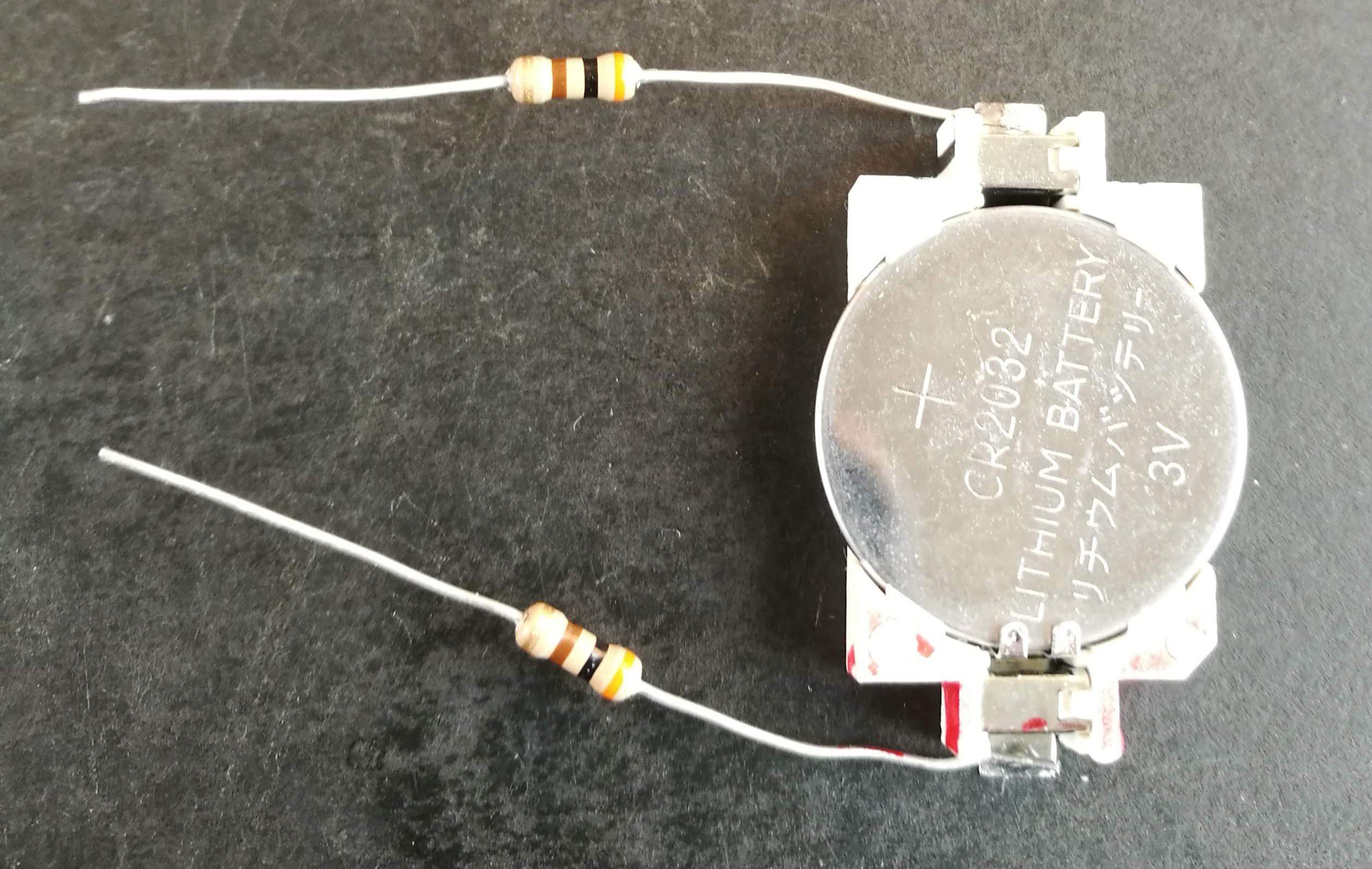
As you can see, the 2018 model was a very clever use of what was on hand. A CR2032 holder powered the probes and the probes themselves were two resistors. If you can get the LED to light with the probes you know which lead is the anode and which is the cathode. A little red ink makes it even more obvious. Continue reading “Supercon SMD Challenge Gets 3D Printed Probes: Build Your Own”

Custom Nixies Perform When Cranked Up To 100,000 Hertz

With the popularity of Nixie clocks, we’d be forgiven for thinking that the glowing tubes are only good for applications with a stately pace of change. But we forget that before they became the must-have hobbyist accessory, Nixies were used in all kinds of scientific instruments, from frequency counters to precision multimeters. In such applications, update rates in the hundreds or thousands of Hertz aren’t uncommon, and the humble Nixie handled display refreshes with ease.

But what about refreshing a Nixie at 100 kHz? That was the question put to artisanal Nixie maker [Dalibor Farný] by a client who wanted a timer to calibrate high-speed cameras. It was a feat that [Dalibor] wasn’t sure his custom-made tubes could handle. The video below shows his efforts to find out.

If you ever wanted to know about the physics of gas-discharge displays like the Nixie, the fifteen minutes starting at about 5:13 will give you everything you need. That basic problem boils down to the half-life of excited neon, or how long it takes for half the population of excited molecules to return to the ground state. That, in turn, dictates how long a given cathode will continue to visibly glow after it’s turned off, which determines how many digits will appear illuminated at once.

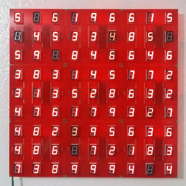
To answer that, they engaged a company in Prague with a camera capable of a mind-blowing 900,000 frames per second. Even though they found a significant afterglow period for each cathode, even at 100 kHz it’s clear which digit is the one that’s currently illuminated. They also looked at the startup of digits in a cold Nixie versus one that’s warmed up, leading to some fascinating footage at around 26:30.

We appreciate [Dalibor]’s attention to detail, not only in the craftsmanship of his custom tubes but in making sure they’re going to do their job. He recently did a failure analysis on some of his high-end clocks that showed the same care for his product and his brand.

Continue reading “Custom Nixies Perform When Cranked Up To 100,000 Hertz”

WWII Aircraft Radio Roars To Life: What It Takes To Restore A Piece Of History

I’ve been told all my life about old-timey Army/Navy surplus stores where you could buy buckets of FT-243 crystals, radio gear, gas masks, and even a Jeep boxed-up in a big wooden crate. Sadly this is no longer the case. Today surplus stores only have contemporary Chinese-made boots, camping gear, and flashlights. They are bitterly disappointing except for one surplus store that I found while on vacation in the Adirondacks: Patriot of Lake George.

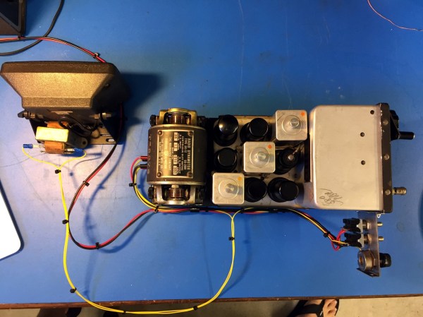
There I found a unicorn of historical significance; an un-modified-since-WW2 surplus CBY-46104 receiver with dynamotor. The date of manufacture was early-war, February 1942. This thing was preserved as good as the day it was removed from its F4F Hellcat. No ham has ever laid a soldering iron or a drill bit to it. Could this unit have seen some action in the south Pacific? Imagine the stories it could tell!

My unconventional restoration of this radio followed strict rules so as to minimize the evidence of repair both inside and out yet make this radio perform again as though it came fresh off the assembly line. Let’s see how I did.

Continue reading “WWII Aircraft Radio Roars To Life: What It Takes To Restore A Piece Of History”

Sleeper PlayStation Hides A Raspberry Pi 4

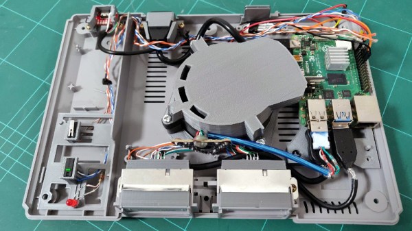
[Andreas Wilcox] wanted to get his brother a birthday gift that reflected their shared love for the early days of 3D gaming, but just handing him a second-hand original PlayStation lacked a certain style. So he decided to gut the classic system and replace its dated internals with a shiny new Raspberry Pi 4. But rather than taking the easy way out, he put in the time and effort to integrate the new hardware so seamlessly that the nearly 25 year old console still looks stock from the outside.

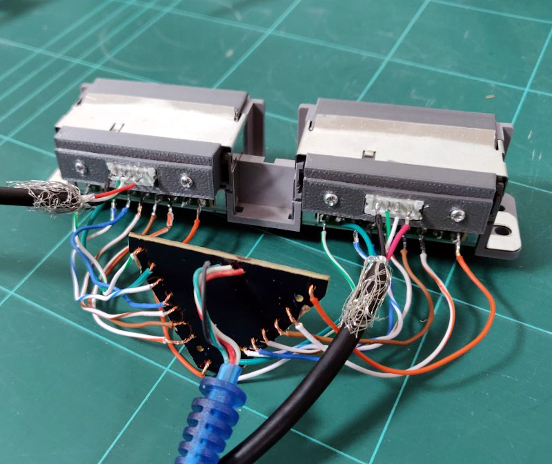
The fact that the front ports are functional and work with the original controllers really helps sell the stock look. [Andreas] found a USB to PlayStation controller adapter, liberated the PCB, and soldered it to the back of the system’s ports. Even the memory card slots got in on the action, thanks to female USB connectors installed where the original connector went. It was a tight fit, but the final result was well worth it.

We also love the GPIO-controlled cooling fan complete with a duct designed to blow across the notoriously toasty Pi, and check out that carefully designed holder for the power and reset buttons. This entire project is really a fantastic example of how 3D printed parts can give your projects a far cleaner and more professional look than the hacker’s old standby of hot glue; though of course it demands a considerable time investment.

This isn’t the first time we’ve seen a Raspberry Pi shoehorned into a classic video game console, but it’s absolutely one of the cleanest examples we’ve ever seen. Though if we lump Raspberry Pi portables into the running, the competition is considerably fiercer.

Are You Getting Your Money’s Worth From Threaded Inserts?

Have you ever wondered whether it’s worth the time and expense to install threaded inserts into your 3D-printed projects? [Stefan] from CNC Kitchen did, and decided to answer the question once and for all, with science.

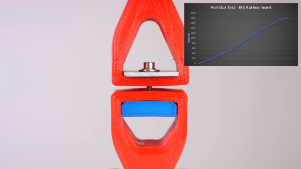
If this sounds familiar, it’s with good reason: we covered [Stefan]’s last stab at assessing threaded inserts back in March. Then, he was primarily interested in determining if threaded inserts are better than threads cut or printed directly into parts. The current work is concerned with the relative value of different designs of threaded inserts. He looked at three different styles of press-in inserts, ranging in price from pennies apiece to a princely 25 cents. The complexity of the outside knurling seems not to be correlated with the price; the inserts with opposed helical knurls seem like they’d be harder to manufacture than the ones with simple barbs on the outside of the barrel, but cost less. And in fact, the mid-price insert outperformed the expensive one in pull-out tests. Surprisingly, the cheapest inserts were actually far worse at pull-out resistance than printing undersized holes and threading an M3 screw directly into the plastic.

[Stefan] also looked at torque resistance, and found no substantial difference between the three insert types. Indeed, none of the inserts proved to be the weak point, as the failure mode of all the torque tests was the M3 bolt itself. This didn’t hold with the bolt threaded directly into the plastic, of course; any insert is better than none for torque resistance.

We enjoyed seeing [Stefan]’s tests, and appreciate the data that can help us be informed consumers. [John] over at Project Farm does similar head-to-head tests, like this test of different epoxy adhesives.

Continue reading “Are You Getting Your Money’s Worth From Threaded Inserts?”