The Hot And Cold Of Balanced Audio

A few summers of my misspent youth found me working at an outdoor concert venue on the local crew. The local crew helps the show’s technicians — don’t call them roadies; they hate that — put up the show. You unpack the trucks, put up the lights, fly the sound system, help run the show, and put it all back in the trucks at the end. It was grueling work, but a lot of fun, and I got to meet people with names like “Mister Dog Vomit.”

One of the things I most remember about the load-in process was running the snakes. The snakes are fat bundles of cables, one for audio and one for lighting, that run from the stage to the consoles out in the house. The bigger the snakes, the bigger the show. It always impressed me that the audio snake, something like 50 yards long, was able to carry all those low-level signals without picking up interference from the AC thrumming through the lighting snake running right alongside it, while my stereo at home would pick up hum from the three-foot long RCA cable between the turntable and the preamp.

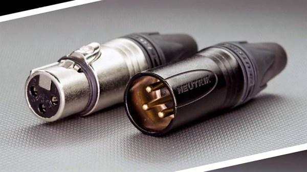
I asked one of the audio techs about that during one show, and he held up the end of the snake where all the cables break out into separate connectors. The chunky silver plugs clinked together as he gave his two-word answer before going back to patching in the console: “Balanced audio.”

Continue reading “The Hot And Cold Of Balanced Audio”

Behind The Pin: How The Raspberry Pi Gets Its Audio

Single board computers have provided us with a revolution in the way we approach computing as hardware creators. We have grown accustomed to a world in which an entire microcomputer has become a component in its own right rather than a complex system, and we interface to them as amorphous entities through their exposed interfaces. But every pin or socket on a single board computer has something behind it, so following up on a recent news-inspired item in which we took a look at what lies behind the Ethernet jack on a Raspberry Pi, we’d like to continue that theme by looking behind more pins and interfaces. So today we’ll stay with the Raspberry Pi, and start with an easy target by taking a look down its audio jack.

All the main Raspberry Pi board releases since 2012 with the exception of the Pi Zero series, have featured a 3.5mm jack carrying line-level audio. The circuits are readily accessible via the Raspberry Pi website, and are easy enough to understand because of course all the really hard work is done within the silicon of the Broadcom system-on-chip. Looking at the audio circuitry, we’ll start by going back to the original Pi Model B from 2012 (PDF) because though more recent models have seen a few changes, this holds the essence of the circuitry.

Continue reading “Behind The Pin: How The Raspberry Pi Gets Its Audio”

Hybrid Lab Power Supply From Broken Audio Amp

The lab power supply is an essential part of any respectable electronics workbench. However, the cost of buying a unit that has all the features required can be eye-wateringly high for such a seemingly simple device. [The Post Apocalyptic Inventor] has showed us how to build a quality bench power supply from the guts of an old audio amplifier.

We’ve covered our fair share of DIY power supplies here at Hackaday, and despite this one being a year old, it goes the extra mile for a number of reasons. Firstly, many of the expensive and key components are salvaged from a faulty audio amp: the transformer, large heatsink and chassis, as well as miscellaneous capacitors, pots, power resistors and relays. Secondly, this power supply is a hybrid. As well as two outputs from off-the-shelf buck and boost converters, there is also a linear supply. The efficiency of the switching supplies is great for general purpose work, but having a low-ripple linear output on tap for testing RF and audio projects is really handy.

The addition of the linear regulator is covered in a second video, and it’s impressively technically comprehensive. [TPAI] does a great job of explaining the function of all the parts which comprise his linear supply, and builds it up manually from discrete components. To monitor the voltage and current on the front panel, two vintage dial voltmeters are used, after one is converted to an ammeter. It’s these small auxiliary hacks which make this project stand out – another example is the rewiring of the transformer secondary and bridge rectifier to obtain a 38V rail rated for twice the original current.

The Chinese DC-DC switching converters at the heart of this build are pretty popular these days, in fact we’re even seeing open source firmware being developed for them. If you want to find out more about how they operate on a basic level, here’s how a buck converter works, and also the science behind boost converters.

Continue reading “Hybrid Lab Power Supply From Broken Audio Amp”

A Guide To Audio Amps For Radio Builders

For hams who build their own radios, mastering the black art of radio frequency electronics is a necessary first step to getting on the air. But if voice transmissions are a goal, some level of mastery of the audio frequency side of the equation is needed as well. If your signal is clipped and distorted, the ham on the other side will have trouble hearing you, and if your receive audio is poor, good luck digging a weak signal out of the weeds.

Hams often give short shrift to the audio in their homebrew transceivers, and [Vasily Ivanenko] wants to change that with this comprehensive guide to audio amplifiers for the ham. He knows whereof he speaks; one of his other hobbies is jazz guitar and amplifiers, and it really shows in the variety of amps he discusses and the theory behind them. He describes a number of amps that perform well and are easy to build. Most of them are based on discrete transistors — many, many transistors — but he does provide some op amp designs and even a design for the venerable LM386, which he generally decries as the easy way out unless it’s optimized. He also goes into a great deal of detail on building AF oscillators and good filters with low harmonics for testing amps. We especially like the tip about using the FFT function of an oscilloscope and a signal generator to estimate total harmonic distortion.

The whole article is really worth a read, and applying some of these tips will help everyone do a better job designing audio amps, not just the hams. And if building amps from discrete transistors has you baffled, start with the basics: [Jenny]’s excellent Biasing That Transistor series.

[via Dangerous Prototypes]

Bike Helmet Plays Music Via Tiny Motors For Bone Conduction

[Matlek] had an interesting problem. On one hand, a 40 minute bike commute without music is a dull event but in France it is illegal for any driver to wear headphones. What to do? Wanting neither to break the law nor accept the risk of blocking out surrounding sounds by wearing headphones anyway, and unwilling to create noise pollution for others with a speaker system, [Matlek] decided to improvise a custom attachment for a bike helmet that plays audio via bone conduction. We’ll admit that our first thought was a worrisome idea of sandwiching metal surface transducers between a helmet and one’s skull (and being one crash away from the helmet embedding said transducers…) but happily [Matlek]’s creation is nothing of the sort.

A 3D printed rack and pinon provides adjustability and stable contact with the “sweet spot” behind each ear.

The bone conduction is cleverly achieved by driving small DC motors with an audio signal through a TPA2012 based audio amplifier, which is powered by a single 18650 cell. By using motors in place of speakers, and using a 3D printed enclosure to hold the motors up to a sweet spot just behind the ears, it’s possible to play music that only the wearer can hear and does not block environmental sounds.

[Matlek] didn’t just throw this together, either. This design was the result of researching bone conduction audio, gathering a variety of different components to use as transducers, testing which performed best, and testing different locations on the body. Just behind the ear was the sweet spot, with the bony area having good accessibility to a helmet-mounted solution. Amusingly, due to the contact between the motors and the rest of the hardware, the helmet itself acts as a large (but weak) speaker and faint music is audible from close range. [Matlek] plans to isolate the motors from the rest of the assembly to prevent this.

Another good way to get audio to transmit via bone conduction? Send it through the teeth. While maybe not the best option for a bike rider, biting down on this metal rod sends audio straight to your inner ear.

Serial Connection Over Audio: Arduino Can Listen To UART

We’ve all been there: after assessing a problem and thinking about a solution, we immediately rush to pursue the first that comes to mind, only to later find that there was a vastly simpler alternative. Thankfully, developing an obscure solution, though sometimes frustrating at the time, does tend to make a good Hackaday post. This time it was [David Wehr] and AudioSerial: a simple way of outputting raw serial data over the audio port of an Android phone. Though [David] could have easily used USB OTG for this project, many microcontrollers don’t have the USB-to-TTL capabilities of his Arduino – so this wasn’t entirely in vain.

At first, it seemed like a simple task: any respectable phone’s DAC should have a sample rate of at least 44.1kHz. [David] used Oboe, a high performance C++ library for Android audio apps, to create the required waveform. The 8-bit data chunks he sent can only make up 256 unique messages, so he pre-generated them. However, the DAC tried to be clever and do some interpolation with the signal – great for audio, not so much for digital waveforms. You can see the warped signal in blue compared to what it should be in orange. To fix this, an op-amp comparator was used to clean up the signal, as well as boosting it to the required voltage.

Prefer your Arduino connections wireless? Check out this smartphone-controlled periodic table of elements, or this wireless robotic hand.

Continue reading “Serial Connection Over Audio: Arduino Can Listen To UART”

Stomping On Microcontrollers: Arduino Mega Guitar Effects Pedal

Effects pedals: for some an object of overwhelming addiction, but for many, an opportunity to hack. Anyone who plays guitar (or buys presents for someone who does) knows of the infinite choice of pedals available. There are so many pedals because nailing the tone you hear in your head is an addictive quest, an itch that must be scratched. Rising to meet this challenge are a generation of programmable pedals that can tweak effects in clever ways.

With this in mind, [ElectroSmash] are back at it with another open source offering: the pedalSHIELD MEGA. Aimed at musicians and hackers who want to learn more about audio, DSP and programming, this is an open-hardware/open-software shield for the Arduino MEGA which transforms it into an effects pedal.

The hardware consists of an analog input stage which amplifies and filters the incoming signal before passing it to the Arduino, as well as an output stage which does the DAC-ing from the Arduino’s PWM outputs, and some more filtering/amplifying. Two 8-bit PWM outputs are used simultaneously to make pseudo 16-bit resolution — a technique you can read more about in their handy forum guide.

The list of effects currently implemented covers all the basics you’d expect, and provides a good starting point for writing custom effects. Perhaps a library for some of the commonly used config/operations would be useful? Naturally, there are some computational constraints when using an Arduino for DSP, though it’s up to you whether this is a frustrating fact, or an opportunity to write some nicely optimised code.

[ElectroSmash] don’t just do pedals either: here’s their open source guitar amp.

Continue reading “Stomping On Microcontrollers: Arduino Mega Guitar Effects Pedal”