The build uses an ATtiny13 to generate pulses for the original hardware, when receiving inputs from the tikkenteller’s buttons. A solid state relay is triggered by the microcontroller, which connects the original solenoid to mains power to jog the counter. An HLK-PM01 5V power supply is used to run the micro, allowing the entire project to run off a single mains supply.
It’s a big, heavy, beautiful hunk of metal, built in a style that we simply don’t see anymore. It’s in no way the cheapest or most efficient counter you could build, but it’s got a charm you can’t find on more modern hardware. You could use such a device to track your Youtube subs, that is… if the API hadn’t broken that for everyone. Video after the break.
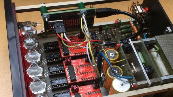
Whenever a project calls for displaying numbers, a 7-segment display is the classic and straightforward choice. However, if you’re more into a rustic, retro, almost mystical, and steampunky look and feel, it’s hard to beat the warm, orange glow of a Nixie tube. Once doomed as obsolete technology of yesteryear, they have since reclaimed their significance in the hobbyist space, and have become such a frequent and deliberate design choice, that it’s easy to forget that older devices actually used them out of necessity for lack of alternatives. Exhibit A: the impulse counter [soldeerridder] found in the attic that he turned into a general-purpose, I2C controlled display.
Instead of just salvaging the Nixie tubes, [soldeerridder] kept and re-used the original device, with the goal to embed an Intel Edison module and connect it via I2C. Naturally, as the counter is a standalone device containing mainly just a handful of SN74141 drivers and SN7490 BCD counters, there was no I2C connectivity available out of the box. At the same time, the Edison would anyway replace the 7490s functionality, so the solution is simple yet genius: remove the BCD counter ICs and design a custom PCB containing a PCF8574 GPIO expander as drop-in replacement for them, hence allowing to send arbitrary values to the driver ICs via I2C, while keeping everything else in its original shape.
Containing six Nixie tubes, the obvious choice is of course to use it as a clock, but [soldeerridder] wanted more than that. Okay, it does display the time, along with the date, but also some sensor values and even the likes on his project blog. If you want to experiment with Nixie tubes yourself, but lack a matching device, Arduino has you obviously covered. Although, you might as well go the other direction then.
Of all the things you never would have guessed you’d need just ten years ago, a YouTube subscriber counter would probably rank highly. You would have guessed that the little hits of dopamine accompanying each tick upward of a number would be so addictive?
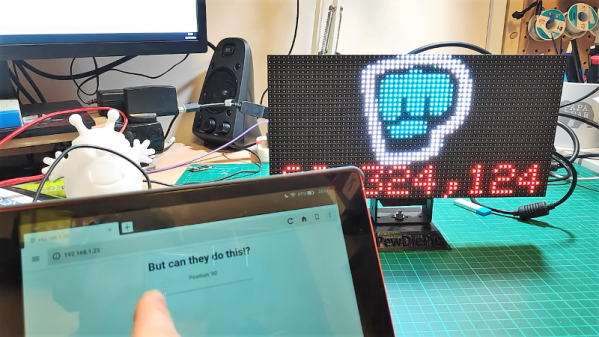
As it turns out, lots of people wanted to keep a running total of their online fans, and a bewilderingly varied ecosystem of subscriber counters has cropped up. All of them rely on the API that YouTube exposes for such purposes, which as [Brian Lough] points out is about to change and break every subscription counter ever made. In the YouTube sub counter space, [Brian] is both an enabler – he built an Arduino wrapper to fetch YT sub counts easily – and a serial builder of displays for other YouTubers. The video below shows a collection of his work, many based on RGB LED matrix display, like the one used in his Tetris-themed sub counter. They’re all well-built, nice to look at, and sadly, destined for obsolescence sometime in August when the API changes.
The details of the API changes were made public in April, and for the subs count it amounts to rounding the count and displaying large counts as, for instance, 510k as opposed to 510,023. We’re confident that [Brian] and other display builders will be able to salvage some of their counters with code changes, but others will probably require hardware changes. Thanks, YouTube.
We all know CERN as that cool place where physicists play with massive, superconducting rings to smash atoms and subatomic particles to uncover secrets of matter in the Universe. To achieve this aim, they need to do a ton of research in other areas, such as development of special particle detectors.
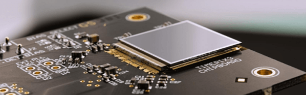
While such developments are essential to the core research needs of the Centre, they also lead to spinoff applications for the benefit of society at large. One such outcome has been the Medipix Collaborations – a family of read-out chips for particle imaging and detection that can count single photons, allowing X-rays and gamma rays to be converted to electrical signals. It may not be possible for us hackers to get our hands on these esoteric sensors, but these devices are pretty interesting and deserve a closer look. Medipix sensors work like a camera, detecting and counting each individual particle hitting the pixels when its electronic shutter is open. This enables high-resolution, high-contrast, noise hit free images – making it unique for imaging applications.
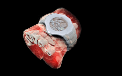
Some months back, CERN announced the first 3D color X-ray of a human made possible using the Medipix devices. The result is a high-resolution, 3D, color image of not just living structures like bones, muscular tissues and vessels, but metal objects too like the wrist watch, seen in the accompanying photograph. The Medipix sensors have been in development since the 1990’s and are presently in their 4th “generation”. Each chip consists of a top semiconducting sensor array, made from gallium arsenide or cadmium telluride. The charge collected by each pixel is transported to the CMOS ASIC electronics via “bump bonds”. The integration is vertical, with each sensing pixel connected via the bump bond to an analog section followed by a digital processing layer. Earlier versions were limited, by technology, in their tiling ability for creating larger matrices of multiple sensors. They could be abutted on three sides only, with the fourth being used for on-chip peripheral logic and wire-bond pads that permit electronic read-out. The latest Medipix4 Collaboration, still under some development, eliminates this short coming. Through-silicon-via (TSV) technology provides the possibility of reading the chips through copper-filled holes that bring the signals from the front side of the chip to its rear. All communication with the pixel matrix flows through the rear of the chip – the peripheral logic and control elements are integrated inside the pixel matrix.
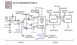
The Analog front end consists of a pre-amplifier followed by a window discriminator which has upper and lower threshold levels. The discriminator has four bits for threshold adjustment as well as polarity sensing. This allows the capture window to be precisely set. The rest of the digital electronics – multiplexers, shift registers, shutter and logic control – helps extract the data.
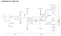
Further development of the Medipix (Tech Brief, PDF) devices led to a separate version called Timepix (Tech Brief, PDF). These new devices, besides being able to count photons, are capable of two additional modes. The first mode records “Time-Over-Threshold”, providing rough analog information about the energy of the photon. It does this by counting clock pulses for the duration when the signal stays above the discrimination levels. The other mode, “Time of Arrival”, measures arrival time of the first particle to impinge on the pixel. The counters record time between a trigger and detection of radiation quanta with energy above the discrimination level, allowing time-of-flight applications in imaging.
Medipix3 pixel schematic
Timepix2 pixel schematic
Besides medical imaging, the devices have applications in space, material analysis, education and of course, high energy physics. Hopefully, in a few years, hackers will lay their hands on these interesting devices and we can get to know them better. At the moment, the Medipix website has some more details and data sheets if you would like to dig deeper. For an overview on the development of such single photon detectors, check out this presentation from CERN – “Single X-Ray Photon Counting Systems: Existing Systems, Systems Under Development And Future Trends” (PDF).
When building projects with a simple goal in mind, it’s not unheard of for us to add more and more switches, buttons, and complexity as the project goes through its initial prototyping stages. Feature creep like this tends to result in a tangled mess rather than a usable project. With enough focus, though, it’s possible to recognize when it’s happening and keep to the original plans. On the other hand, this single-button project with more than one use seems to be the opposite of feature creep. (YouTube, embedded below.)
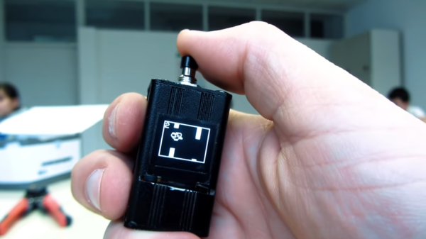
[Danko]’s project has one goal: be as useful as possible while only using a single button and a tiny screen. Right now the small handheld device can be used as a stopwatch, a counter, and can even play a rudimentary version of flappy bird. It uses an Arduino Pro Mini, a 64×48 OLED screen running on I2C, and has a miniscule 100 mAh 3.7V battery to power everything. The video is worth watching if you’ve never worked with this small of a screen before, too.
Getting three functions out of a device with only one button is a pretty impressive feat, and if you can think of any other ways of getting more usefulness out of something like this be sure to leave it in the comments below. [Danko] is no stranger to simple projects with tiny screens, either. We recently featured his homebrew Arduino calculator that uses an even smaller screen.
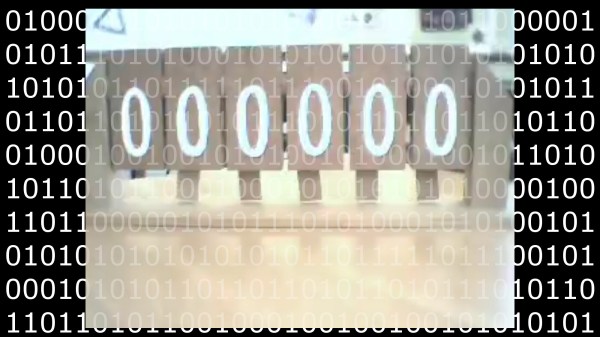
If you are familiar with binary, what would you need to teach someone who only knows decimal? If you do not know how to count in binary, let us know if the video below the break helps you understand how the base-2 number system works. If learning or counting binary is not what you are interested in, maybe you can appreciate the mechanics involved with making a counter that cycles through all the ones and zeros (links to the video shown below). The mechanism is simple enough. A lever at the corner of each “1” panel is attached off-center, so it hangs when it is upside-down, then falls to the side when it is upright, so it can swivel the adjacent panel.
Perhaps this is a desktop bauble to show off your adeptness at carpentry, or skills with a laser cutter, or 3D printer. No matter what it is made out of, it will not help you get any work done unless you are a teacher who wants to demonstrate the discrete nature of binary. If wood and bits are up your alley, we have a gorgeous binary driftwood clock to feast your eyes on. Meanwhile if analog methods of working digital numbers suit you, we have binary math performed with paper models.
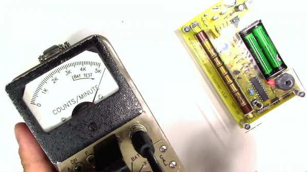
There are times in one’s life when circumstances drive an intense interest in one specific topic, and we put our energy into devouring all the information we can on the subject. [The Current Source], aka [Derek], seems to be in such a situation these days, and his area of interest is radioactivity and its measurement. So with time to spare on his hands, he has worked up this video review of radioactivity and how Geiger counters work.
Why the interest in radioactivity? Bluntly put, because he is radioactive, at least for the next week. You see, [Derek] was recently diagnosed with thyroid cancer, and one of the post-thyroidectomy therapeutic options to scavenge up any stray thyroid cells is drinking a cocktail of iodine-131, a radioisotope that accumulates in thyroid cells and kills them. Trouble is, this leaves the patient dangerously radioactive, necessitating isolation for a week or more. To pass the time away from family and friends, [Derek] did a teardown on a commercial Geiger counter, the classic Ludlum Model 2 with a pancake probe. The internals of the meter are surprisingly simple, and each stage of the circuit is easily identified. He follows that up with a DIY Geiger counter kit build, which is also very simple — just a high-voltage section made from a 555 timer along with a microcontroller. He tests both instruments using himself as a source; we have to say it’s pretty alarming to hear how hot he still is. Check it out in the video below.
Given the circumstances, we’re amazed that [Derek] is not only keeping his cool but exhibiting a good sense of humor. We wish him well in his recovery, and if doing teardowns like this or projects like this freezer alarm or a no-IC bipolar power supply helps him cope, then we all win.

 Some months back, CERN announced
 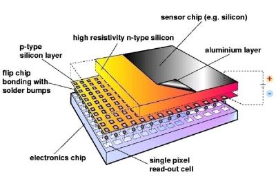 The Analog front end consists of a pre-amplifier followed by a window discriminator which has upper and lower threshold levels. The discriminator has four bits for threshold adjustment as well as polarity sensing. This allows the capture window to be precisely set. The rest of the digital electronics – multiplexers, shift registers, shutter and logic control – helps extract the data.