A Breath Of Fresh Air For Some Arcade Classics

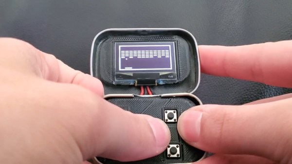
It’s said that good things come in small packages, which is hard to deny when we look at all the nifty projects out there that were built into an Altoids tin. Now, if that’s already true for the regular sized box, we can be doubly excited for anything crammed into their Smalls variety ones, which is what [Kayden Kehe] decided to use as housing for his mintyPico, a tiny gaming console running homebrew versions of Snake, Breakout, Pong, and a few more.

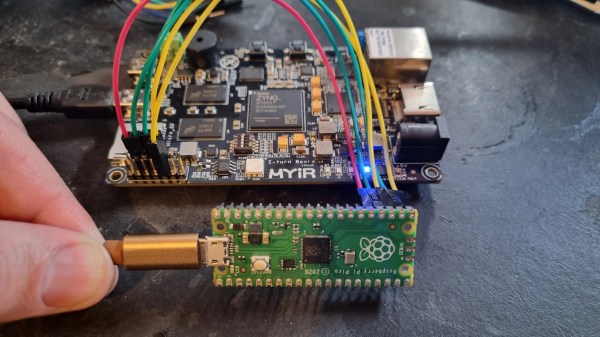
As the “Pico” might have already given away, the project is built around a Raspberry Pi Pico board, and being intended as portable device, [Kayden] went with a version that also houses LiPo battery charging circuitry. A set of 3d-printed parts pack the board along with a matching battery and a button panel neatly into the tin itself, while a size-appropriate SSH1106 OLED goes into the lid. All design files along with the MicroPython code of the games can be found on the project’s GitHub page.

You may have felt this strange sense of familiarity when you read the project’s name, and indeed, the mintyPi gaming console was a major inspiration for [Kayden] here, as was the Pico Snake project. Considering this was his junior year high school project, this is certainly an impressive and nice mash-up of those two projects.

Continue reading “A Breath Of Fresh Air For Some Arcade Classics”

Electronic Catan Game Board Is Modular

Plenty of gamers around these parts require an expensive PC to play games, often spending thousands of dollars for a gaming machine. Believe it or not, though, there are entire classes of games that don’t require any electronics at all, but that doesn’t mean that they don’t benefit from the addition of some neat gadgets. This Settlers of Catan game uses custom LCD tiles with a built-in custom mesh network.

The tiles for the game board themselves are hexagonal and snap together using magnetic pogo pins in order to form a board of any size or shape. The pogo pins also allow communication for a pseudo-mesh network to operate with each tile’s built-in PCB to allow the game board to know exactly which tiles are placed where and to display the correct image on each one. Each tile contains it own RP2040 microcontroller, keeping the overall cost of each tile to a minimum.

For those regularly hosting game night, a project like this could really change the traditionally analog game’s dynamic for the better. It was mostly a project that [Colin Iuliano] built just for fun, and if he ever builds a second one he does plan on some improvements, but we’d say that it looks like a success already. For other Catan-based electronic design inspiration, take a look at this complete and non-modular electronic game board.

Console Macropad Uses SD Cards For Stylin’ And Profilin’

Macropads are great to have around for hotkey input, but things can get out of hand pretty quickly when you realize just how many shortcuts are in your life. To avoid ending up with another keyboard-sized keyboard, some hackers will use a handful of switches and a lot of layers to turn a few keys into many. And instead of worrying about legends, they use blank keys and leave the labels to be displayed on some kind of screen.

Among them is [QCJ3], who built this nifty little console-style macropad. Uninterested in managing microcontroller memory, [QCJ3] went the tangible route and loaded various profiles onto a micro SD card. Each text file on a given card holds a label, a color for the keyswitch LED, and of course, the keystrokes that make up the macro itself.

There are myriad ways to build a macro pad, from designing with bare chips (if you can get them) to programming a pre-built key matrix.  Grab the files if you like the console look and call it a day, or build a completely new enclosure that fits your hand exactly. Whatever you build, consider entering it in our brand spankin’ new Odd Inputs and Peculiar Peripherals Contest, which runs now through July 4th. If you need more inspiration, just peep the projects under macropad tag, or peruse the much heftier keyboard tag.

Via KBD

Number Like It’s 1234 AD With This Cistercian Keypad

Don’t feel bad if you don’t know what Cistercian numbers are. Unless you’re a monk of the Order of Cistercia, there’s really no reason for you to learn the cipher that stretches back to the 13th-century. But then again, there’s no reason not to use the number system to make this medieval-cool computer number pad.

If you haven’t been introduced to the Cistercian number system, it’s actually pretty clever. There are several forms of it, but the vertical form used here by [Tauno Erik] is based on a vertical stave with nine glyphs that can be attached to or adjacent to it. Each glyph stands for one of the nine numerals — one through nine only; there’s no need for a zero glyph. There are four quadrants around the stave — upper right, upper left, lower right, and lower left — and where the glyph lies determines the multiplier for the glyph. So, if you wanted to write the number “1234”, you’d overlay the following glyphs into a single symbol as shown.

[Tauno]’s Cistercian keypad, admittedly more of an art and history piece than a useful peripheral, somehow manages to look like it might have been on the desk of [Theodoric of York, Medieval Accountant]. Its case is laser-cut birch plywood, containing a custom PCB for the 20 keyboard switches and the Xiao RP2040 MCU that runs the show. Keycaps are custom made from what looks like oak combined with a 3D-printed part, similar to his previous wooden keycap macro pad. Each of the nine Cistercian glyphs is hand-carved into the keycaps, plus an imaginary glyph for zero, which wasn’t part of the system, as well as operators and symbols that might have baffled the medieval monks.

The native Cistercian system is limited to numbers between 1 and 9,999, so we’ll guess that the keypad just outputs the Arabic numeral corresponding to the Cistercian key pressed and doesn’t actually compose full Cistercian numbers. But the code to do that would be pretty easy, and the results pretty cool, if a bit confusing for users. Even if it’s just for looks, it’s still a cool project, and we doff the hood of our monkish robe to [Tauno] for this one.

The TinyPICO board and the rocker switch soldered together showing a complete device, shown being held in the air by a crocodile clip

Simple Hardware Switch For OS Dualbooting, Thanks To RP2040

Dualbooting your computer can be a chore, the more switching between OSes you have to do – which is why virtualization or having separate computers are the go-to for many. Failing that, we have no choice but to smooth over our dualbooting experience with various workarounds and helpers. [William Somsky] shares one such helper tool with us – an elegant device made with a RP2040-sporting TinyPICO board and a three-way rocker switch, directing GRUB to boot into either Windows or Linux automatically, or leave us with the usual boot menu. This way, you can just flip the switch, hit “reboot” and walk away, coming back to your PC booted into OS of your choice, instead of timing your presence just so that you can catch the boot menu on time.

All you need to do is to solder a rocker switch to your RP2040 board of choice, then flash the RP2040 with code that detects the state of the switch, and creates a mass storage device hosting a file setting a Grub variable to either one of the 0, 1 or 2. [William] describes his journey, fighting mysterious caching problems, but tells us he got it working in the end. Sadly, [William] hasn’t shared the RP2040-side code with us, but he has at least put the Grub’s custom.cfg file in the ‘Files’ section of the Hackaday.io project.

Readily accessible microcontrollers with mass storage functions sure help make such hacks simple – earlier, we’ve seen dualboot switching like this done by modifying assembly code of the MBR. Dualbooting is a hacker’s rite of passage, and certain OSes of late can make it harder than other ones. Even if you don’t want to dualboot your PC, however, you sure can dualboot an Arduino!

Processing Audio With The RP2040

The Raspberry Pi, although first intended as an inexpensive single-board computer for use in education, is now ubiquitous in electronics communities. Its low price as well as Linux platform and accessible GPIO make it useful in many places outside the classroom. But, if you want to abandon the ease-of-use in favor of an even lower price, the Raspberry Pi foundation makes that possible as well with the RP2040 chip, commonly found on the Pico. [Jason] shows us one way to make use of this powerful chip by putting one in an audio digital signal processing board.

While development boards are available for this chip, [Jason] has opted instead for a custom PCB which he designed himself and includes an integrated headphone amplifier and 3.5 mm audio jacks. To do the actual DSP work, the RP2040 chip uses three 12-bit ADC channels and 16 controllable PWM channels. The platform is also equipped with the TLV320AIC3254 codec from Texas Instruments. With all of this put together, he has a functioning open-source platform he calls the DS-Pi.

[Jason] has built this as a platform for guitar effects and as a customizable guitar amp modeler, but with a platform that is Arduino-compatible and fairly easy to program it could be put to use for anything involving other types of music or audio processing, like this specialized MIDI-compatible guitar effects platform which is built around the same processor.

A Pi Pico connected to a MYIR Z-turn board with a set of jumper wires

Need A JTAG Adapter? Use Your Pico!

JTAG is a powerful interface for low-level debugging and introspection of all kinds of devices — CPUs, FPGAs, MCUs and a whole lot of complex purpose-built chips like RF front-ends. JTAG adapters can be quite obscure, or cost a pretty penny, which is why we’re glad to see that [Adam Taylor] from [ADIUVO] made a tutorial on using your Pi Pico board as a JTAG adapter. This relies on a project called XVC-Pico by [Dhiru Kholia], and doesn’t require anything other than a Pi Pico board itself — the XVC-Pico provides both a RP2040 firmware implementing the XVC (Xilinx Virtual Cable) specification and a daemon that connects to the Pico board and interfaces to tools like Vivado.

First part of the write-up is dedicated to compiling the Pico firmware using a Linux VM. There’s a pre-built .uf2 binary available in the GitHub repo, however, so you don’t have to do that. Then, he compiles and runs a daemon on the PC where the Pico is connected, connects to that daemon through Vivado, and shows successful single-stepping through code on a MYIR Z-turn board with a Xilinx XC7Z020. It’s worth remembering that, if your FPGA’s (or any other target’s) JTAG logic levels are 1.8V or 2.5V-based, you will need a level shifter between it and the Pi Pico, which is a board firmly in the 3.3V realm.

You just cannot beat the $3 price and the ease of setup. Pi Pico is shaping up to be more and more of a hardware multi-tool. Just a month ago, we covered how the Pico can work as a logic analyzer. A lot of that, we have the PIO peripherals to thank for — an assembly of state machines that even let you “bitbang” high-speed interfaces like DVI. If you’re interested in how PIO functions, there are some good write-ups around here. Lacking a Pi Pico, you can use this board’s bigger sister to interface with JTAG, too.