There are those who reckon the humble bowl of breakfast cereal to be the height of culinary achievement. Look askance if you must, but cereal junkies are a thing, and they have a point. The magic comes not from just filling a bowl and adding a splash of milk, but by knowing which cereals to mix together.
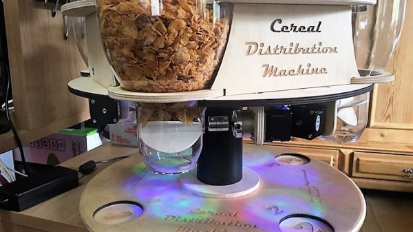
Who needs all that fussy mixing, though, when you can automate and customize your cereal dispensing chores? That’s the approach [Kevin Obermann] and [Adrian Bernhart] took with their Cereal Dispensing Machine, even if they went a little further than necessary. Laser-cut plywood forms a four-station carousel for off-the-shelf dry-good dispensers, each of which got a stepper motor to replace the wrist-twisting. The original motors were a bit too wimpy to handle the more rugged morning selections and were eventually upgraded to gear motors. The platform that supports the dispensers also holds all the electronics, including an ESP32 to run everything and host the web app needed to choose your poison. Plus RGB LEDs, because breakfast should look like a rave. Sadly, the team ran out of GPIO pins and were unable to run the peristaltic pump needed to add the milk. There will always be version 2.0, though.
If cereal isn’t your automated breakfast of choice, we understand. Perhaps a more [Wallace] and [Gromit] style breakfast machine would do, or a robotic peanut butter sandwich any time of day is a treat.
Continue reading “Carousel Of Cereals Mixes And Matches Custom Breakfast Blends”