A pinout diagram of the new Pi 4, showing all the alternate interfaces available.

Did You Know That The Raspberry Pi 4 Has More SPI, I2C, UART Ports?

We’ve gotten used to the GPIO-available functions of Raspberry Pi computers remaining largely the same over the years, which is why it might have flown a little bit under the radar: the Raspberry Pi 4 has six SPI controllers, six I2C controllers, and six UARTs – all on its 40-pin header. You can’t make use of all of these at once, but with up to four different connections wired to a single pin you can carve out a pretty powerful combination of peripherals for your next robotics, automation or cat herding project.

The datasheet for these peripherals is pleasant to go through, with all the register maps nicely laid out – even if you don’t plan to work with the register mappings yourself, the maintainers of your preferred hardware enablement libraries will have an easier time! And, of course, these peripherals are present on the Compute Module 4, too. It might feel like such a deluge of interfaces is excessive, however, it lets you achieve some pretty cool stuff that wouldn’t be possible otherwise.

Having multiple I2C interfaces helps deal with various I2C-specific problems, such as address conflicts, throughput issues, and mixing devices that support different maximum speeds, which means you no longer need fancy mux chips to run five low-resolution Melexis thermal camera sensors at once. (Oh, and the I2C clock stretching bug has been fixed!) SPI interfaces are used for devices with high bandwidth, and with a few separate SPI ports, you could run multiple relatively high-resolution displays at once, No-Nixie Nixie clock style.

As for UARTs, the Raspberry Pi’s one-and-a-half UART interface has long been an issue in robotics and home automation applications. With a slew of devices like radio receivers/transmitters, LIDARs and resilient RS485 multi-drop interfaces available in UART form, it’s nice that you no longer have to sacrifice Bluetooth or a debug console to get some fancy sensors wired up to your robot’s brain. You can enable up to six UARTs. Continue reading “Did You Know That The Raspberry Pi 4 Has More SPI, I2C, UART Ports?” →
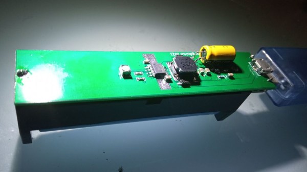
The powerbank PCB, with all the components on one side, 18650 holder on the other, a MicroUSB cable plugged into the PCB's MicroUSB socket

Open Hardware 5V UPS Improves On Cheap Powerbank Design

Often, we need to power a 5V-craving project of ours on the go. So did [Burgduino], and, unhappy with solutions available, designed their own 5V UPS! It takes a cheap powerbank design and augments it with a few parts vital for its UPS purposes.

You might be tempted to reach for a powerbank when facing such a problem, but most of them have a fatal flaw, and you can’t easily tell a flawed one apart from a functioning one before you buy it. This flaw is lack of load sharing – ability to continue powering the output when a charger is inserted. Most store-bought powerbanks just shut the output off, which precludes a project running 24/7 without powering it down, and can cause adverse consequences when something like a Raspberry Pi is involved.

Understandably, [Burgduino] wasn’t okay with that. Their UPS is based on the TP5400, a combined LiIon charging and boost chip, used a lot in simple powerbanks, but not capable of load sharing. For that, an extra LM66100 chip – an “ideal diode” controller is used. You might scoff at it being a Texas Instruments part, but it does seem to be widely available and only a tad more expensive than the TP5400 itself! The design is open hardware, with PCB files available on EasyEDA and the BOM clearly laid out for easy LCSC ordering.

We the hackers might struggle to keep our portable Pi projects powered, employing supercapacitors and modifying badly designed Chinese boards. However, once we find a proper toolkit for our purposes, battery-powered projects tend to open new frontiers – you might even go beyond your Pi and upgrade your router with an UPS addon! Of course, it’s not always smooth sailing, and sometimes seemingly portability-friendly devices can surprise you with their design quirks.

A graph visualising approximation errors - the specific principle pictured is described well by the linked article

Time And Accuracy In Las ATMegas

Do you ever have to ensure that an exact amount of time passes between two tasks in your microcontroller code? Do you know what’s the difference between precision and accuracy? Today, [Jim Mack] tells us about pushing timers and interrupts to their limits when it comes to managing time, while keeping it applicable to an ever-popular ATMega328P target! Every now and then, someone decides to push the frontiers of what’s possible on a given platform, and today’s rules is coding within constraints of an Arduino environment. However, you should check [Jim]’s post out even if you use Arduino as a swearword – purely for all of the theoretical insights laid out, accompanied by hardware-accurate examples!

This will be useful to any hacker looking to implement, say, motor encoder readings, signal frequency calculations, or build a gadget processing or modifying audio in real time. To give you a sample of this article, [Jim] starts by introducing us to distinctions between precision and accuracy, and then presents us with a seemingly simple task – creating exactly 2400 interrupts a second. As much as it might look straightforward, problems quickly arise when clock crystal frequency doesn’t cleanly divide by the sampling frequency that you have to pick for your application! This is just a taste of all the examples of hidden complexity presented, and they’re accompanied with solutions you can use when you eventually encounter one of these examples in your hacker pursuits. In the end, [Jim] concludes with links to other sources you can study if you ever need to dig deeper into this topic.

Keeping our projects true to the passage of time can be an issue, and we’ve been at it for ages – calibrating your RC oscillator is a rite of passage for any ATTiny project. If you ever decide to have an interrupt peripheral help you with timing issues, we’ve gone in-depth on that topic in the past, with a three-part series describing the benefits, the drawbacks and the edgecases of interrupts. Going for a more modern target? Our piece on using interrupts with STM32 is a great path for trying out tools of the modern age.

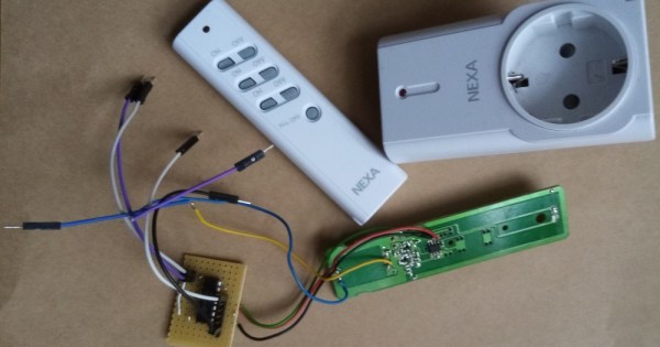
Remote control PCB next to its shell, with a breadboarded analog switch connected to the remote's onboard microcontroller, soldered to the pins responsible for button reading

Reusing Proprietary Wireless Sockets Without Wireless Hacking

Bending various proprietary devices to our will is a hacker’s rite of passage. When it comes to proprietary wall sockets, we’d often reverse-engineer and emulate their protocol – but you can absolutely take a shortcut and, like [oaox], spoof the button presses on the original remote! Buttons on such remotes tend to be multiplexed and read as a key matrix (provided there’s more than four of them), so you can’t just pull one of the pads to ground and expect to not confuse the microcontroller inside the remote. While reading a key matrix, the controller will typically drive rows one-by-one and read column states, and a row or column driven externally will result in the code perceiving an entire group of keys as “pressed” – however, a digitally-driven “switch” doesn’t have this issue!

One way to achieve this would be to use a transistor, but [oaox] played it safe and went for a 4066 analog multiplexer, which has a higher chance of working with any remote no matter the button configuration, for instance, even when the buttons are wired as part of a resistor network. As a bonus, the remote will still work, and you will still be able to use its buttons for the original purpose – as long as you keep your wiring job neat! When compared to reverse-engineering the protocol and using a wireless transmitter, this also has the benefit of being able to consistently work with even non-realtime devices like Raspberry Pi, and other devices that run an OS and aren’t able to guarantee consistent operation when driving a cheap GPIO-operated RF transmitter.

In the past, we’ve seen people trying to tackle this exact issue, resorting to RF protocol hacking in the end. We’ve talked about analog multiplexers and switches in the past, if you’d like figure out more ways to apply them to solve your hacking problems! Taking projects like these as your starting point, it’s not too far until you’re able to replace the drift-y joysticks on your Nintendo Switch with touchpads!

Ray's panels on the wall - circles of different sizes (from 60 to 15cm in diameter) covered by fabric of different shades, their arrangement vaguely resembling a cloud.

DIY Acoustic Panels Or Modern Artwork? Can’t Tell

The acoustic properties of a room have a surprising impact when you want to use a microphone. [RayP24]’s son was trying to make his bedroom into a better recording studio, and for [Ray], that turned into an artfully-executed wall panel project. Fortunately, the process is documented so we all can learn from it. When it comes to acoustics, you can often get a whole lot of improvement from surprisingly few changes. And, as this project demonstrates, you can make it look like a decorative piece to boot.

When arranged and placed on the wall, these panels look like an art piece, a decoration you could get from a somewhat fancy store. If you show them to someone, they might not believe that they also serve as a functioning home acoustics improvement, dampening the sound quite well for audio recording needs. The panels are built out of individual circles, cut out in a way that uses as much of a 3/16″ (5mm) plywood sheet as possible, with hollow circles serving as frames to attach foam-backed fabric. In the Instructables post, [Ray] talks quite a bit about how you can assemble your own and what liberties you can take. There’s also a short video accompanying this project, which you can see after the break. This project is begging to be recreated.

There’s a sizeable amount of hacking-meets-home improvement-meets-home acoustics projects out there, especially lately, when so many people are stuck at home for one reason or another. Just a few months ago, we covered another marvelous “art piece turned reverb killer” project operating by a slightly different principle, and also going a bit more into the theory. Perhaps in a few years, we will no longer have to build panels or structures for our soundproofing needs, as purpose-grown mycelium shapes will do that for us. And once it becomes a question of where to hang your newly-built acoustic panels, this simple guide is a good place to start.

Continue reading “DIY Acoustic Panels Or Modern Artwork? Can’t Tell” →

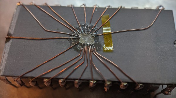
The decapped chip on top of some other DIP IC, with magnet wire soldered to the die, other ends of the magnet wire soldered to pins of the "body donor" DIP IC.

Factory Defect IC Revived With Sandpaper And Microsoldering

We might be amidst a chip shortage, but if you enjoy reverse-engineering, there’s never a shortage of intriguing old chips to dig into – and the 2513N 5×7 character ROM is one such chip. Amidst a long thread probing a few of these (Twitter, ThreadReader link), [TubeTime] has realized that two address lines were shorted inside of the package. A Twitter dopamine-fueled quest for truth has led him to try his hand at making the chip work anyway. Trying to clear the short with an external PSU led to a bond wire popping instead, as evidenced by the ESD diode connection disappearing.

A dozen minutes of sandpaper work resulted in the bare die exposed, making quick work of the bond wires as a side effect. Apparently, having the bond pads a bit too close has resulted in a factory defect where two of the pads merged together. No wonder the PSU wouldn’t take that on! Some X-acto work later, the short was cleared. But without the bond wires, how would [TubeTime] connect to it? This is where the work pictured comes in. Soldering to the remains of the bond wires has proven to be fruitful, reviving the chip enough to continue investigating, even if, it appears, it was never functional to begin with. The thread continued on with comparing ROMs from a few different chips [TubeTime] had on hand and inferences on what could’ve happened that led to this IC going out in the wild.

Such soldering experiments are always fun to try and pull off! We rarely see soldering on such a small scale, as thankfully, it’s not always needed, but it’s a joy to witness when someone does IC or PCB microsurgery to fix factory defects that render our devices inoperable before they were even shipped. Each time that a fellow hacker dares to grind the IC epoxy layers down and save a game console or an unidentified complex board, the world gets a little brighter. And if you aren’t forced to do it for repair reasons, you can always try it in an attempt to build the smallest NES in existence!

Continue reading “Factory Defect IC Revived With Sandpaper And Microsoldering” →

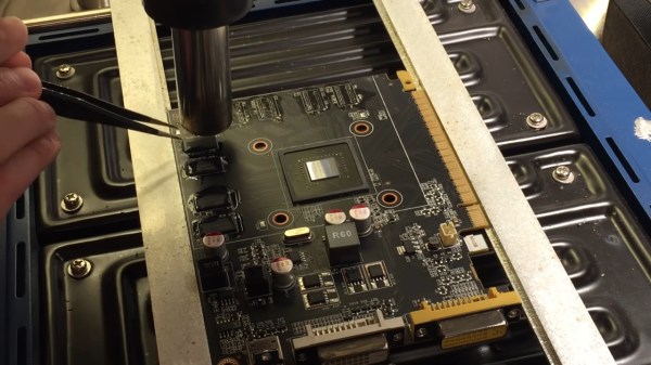
A GPU PCB mounted on top of a preheater, with a hot air gun blowing on top of one of the DDR chips, held with tweezers, about to be removed from the board. Most of the other chips are already gone from the board, with only a few left.

GPU RAM Upgrades Are Closer Than You Think

We’re all used to swapping RAM in our desktops and laptops. What about a GPU, though? [dosdude1] teaches us that soldered-on RAM is merely a frontier to be conquered. Of course, there’s gotta be a good reason to undertake such an effort – in his case, he couldn’t find the specific type of Nvidia GT640 that could be flashed with an Apple BIOS to have his Xserve machine output the Apple boot screen properly. All he could find were 1GB versions, and the Apple BIOS could only be flashed onto a 2GB version. Getting 2GB worth of DDR chips on Aliexpress was way too tempting!

The video goes through the entire replacement process, to the point where you could repeat it yourself — as long as you have access to a preheater, which is a must for reworking relatively large PCBs, as well as a set of regular tools for replacing BGA chips. In the end, the card booted up, and, flashed with a new BIOS, successfully displayed the Apple bootup logo that would normally be missing without the special Apple VBIOS sauce. If you ever want to try such a repair, now you have one less excuse — and, with the GT640 being a relatively old card, you don’t even risk all that much!

This is not the first soldered-in RAM replacement journey we’ve covered recently — here’s our write-up about [Greg Davill] upgrading soldered-in RAM on his Dell XPS! You can upgrade CPUs this way, too. While it’s standard procedure in sufficiently advanced laptop repair shops, even hobbyists can manage it with proper equipment and a good amount of luck, as this EEE PC CPU upgrade illustrates. BGA work and Apple computers getting a second life go hand in hand — just two years ago, we covered this BGA-drilling hack to bypass a dead GPU in a Macbook, and before that, a Macbook water damage revival story.

Continue reading “GPU RAM Upgrades Are Closer Than You Think” →