Cat Robot’s Secret To Slim Legs? Banish The Motors!

The first thing to notice about [Bijuo]’s cat-sized quadruped robot designs (link is in Korean, Google translation here) is how slim and sleek the legs are. That’s because unlike most legged robots, the limbs themselves don’t contain any motors. Instead, the motors are in the main body, with one driving a half-circle pulley while another moves the limb as a whole. Power is transferred by a cable acting as a tendon and is offset by spring tension in the joints. The result is light, slim legs that lift and move in a remarkable gait.

[Bijuo] credits the Cheetah_Cub project as their original inspiration, and names their own variation Mini Serval, on account of the ears and in keeping with the feline nomenclature. Embedded below are two videos, the first showing leg and gait detail, and the second demonstrating the robot in motion.

Continue reading “Cat Robot’s Secret To Slim Legs? Banish The Motors!”

Behold A DIY, Kid-Friendly Table Saw

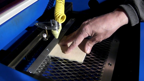
The “table saw” swaps the saw for a nibbler; here it is cutting corrugated cardboard in a manner much like the saw it replaces.

“Kid-friendly table saw” seems like either a contradiction, a fool’s errand, or a lawsuit waiting to happen; but this wooden table saw for kids actually fits the bill and shows off some incredible workmanship and attention to detail as well. The project works by using not a saw blade, but a nibbler attached to a power drill embedded inside.

Unsurprisingly, the key to making a “table saw” more kid-friendly was to remove the saw part. The nibbler will cut just about any material thinner than 3 mm, and it’s impossible for a child’s finger to fit inside it. The tool is still intended for supervised use, of course, but the best defense is defense in depth.

The workmanship on the child-sized “table saw” is beautiful, with even the cutting fence and power switch replicated. It may not contain a saw, but it works in a manner much like the real thing. The cutting action itself is done by an economical nibbler attachment, which is a small tool with a slot into which material is inserted. Inside the slot, a notched bar moves up and down, taking a small bite of any material with every stroke. Embedding this into the table allows for saw-like cutting of materials such as cardboard and thin wood.

The image gallery is embedded below and shows plenty of details about the build process and design, along with some super happy looking kids.

Continue reading “Behold A DIY, Kid-Friendly Table Saw”

Wood Shines In This SCARA Robotic Arm Project

[igarrido] has shared a project that’s been in the works for a long time now; a wooden desktop robotic arm, named Virk I. The wood is Australian Blackwood and looks gorgeous. [igarrido] is clear that it is a side project, but has decided to try producing a small run of eight units to try to gauge interest in the design. He has been busy cutting the parts and assembling in his spare time.

Besides the beautifully finished wood, some of the interesting elements include hollow rotary joints, which mean less cable clutter and a much tidier assembly. 3D printer drivers are a common go-to for CNC designs, and the Virk I is no different. The prototype is driven by a RAMPS 1.4 board, but [igarrido] explains that while this does the job for moving the joints, it’s not ideal. To be truly useful, a driver would need to have SCARA kinematic support, which he says that to his knowledge is something no open source 3D printer driver offers. Without such a driver, the software has no concept of how the joints physically relate to one another, which is needed to make unified and coherent movements. As a result, users must control motors and joints individually, instead of being able to direct the arm as a whole to move to specific coordinates. Still, Virk I might be what’s needed to get that development going. A video of some test movements is embedded below, showing how everything works so far.

Continue reading “Wood Shines In This SCARA Robotic Arm Project”

DIY Switches For People Who Can’t Push Switches

An outstanding number of things most people take for granted present enormous hurdles for people with physical disabilities, including interaction with computers and other digital resources. Assistive technologies such as adaptive switches allow users who cannot use conventional buttons or other input devices to interact with digital devices, and while there are commercial offerings there is still plenty of room for projects like [Cassio Batista]’s DIY Low-cost Assistive Technology Switches.

[Cassio]’s project focuses on non-contact switches, such as proximity and puff-based activations. These are economical, DIY options aimed at improving accessibility for people who are unable to physically push even specialized switches. There are existing products in this space, but cost can be a barrier and DIY options that use familiar interfaces greatly improves accessibility.

Assistive technologies that give people the tools they need to have more control over their own lives in a positive, healthy way is one of the more vibrant and positive areas of open hardware development, and it’s not always clear where the challenges lie when creating solutions. An example of this is the winner of the 2015 Hackaday Prize, the Eyedrivomatic, which allows one to interface the steering of an electric wheelchair to a gaze tracking system while permanently altering neither device; a necessity because users often do not own their hardware.

3D Printed Radius Gauge, Just Add Calipers (And A Wee Bit Of Math)

With 3D printed arms of fixed measurements, the depth reading from a set of digital calipers can be used to calculate the radius of a curve.

Specialized tools that focus on one particular job tend to get distilled right down to their essentials and turned in an economical consumer product. One example of this is radius (or fillet) gauges: a set of curves in different sizes that one uses to measure the radius of a curved surface by trial and error. To some, such products represent solved problems. Others see opportunities for a fresh perspective, like this caliper-enabled 3D printed radius gauge by [Arne Bergkvist].

[Arne]’s 3D printed radius gauge is a simple object; a rigid attachment for a nearly ubiquitous model of digital caliper. By placing the curve to be measured between the two arms of the device and using the depth measurement of the caliper to measure distance to the curve’s surface, a simple calculation (helpfully printed on the unit itself) of radius = distance * 2.414 reveals the radius of the curve. However, this shortened calculation makes a number of assumptions and only works for [Arne]’s specific design.

Another version by [Fredrik Welander] represents a more flexible take on the same concept. His RadGauge design (pictured up top) has a few different sizes to accommodate a variety of objects, and his Git repository provides a calculator tool as well as some tips on fine tuning to allow for variations in the dimensions of the printed attachment.

3D printing has opened a lot of doors, and items like this show that the plastic doodads created aren’t always the end result in and of themselves; sometimes they are the glue that enables a tool or part to work in a different way. To help get the most out of 3D printing, check out the in-depth coverage of how to best tap 3D printed parts for fasteners, and [Roger Cheng]’s guide to using 3D printed brackets and aluminum extrusion to make just about anything.

See The Fabulous Workmanship In This Smart Pressure Regulator

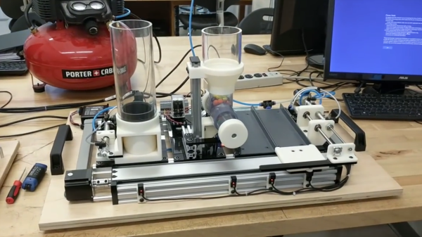
For many projects that require control of air pressure, the usual option is to hook up a pump, maybe with a motor controller to turn it on and off, and work with that. If one’s requirements can’t be filled by that level of equipment and control, then it’s time to look at commercial regulators. [Craig Watson] did exactly that, but found the results as disappointing as they were expensive. He found that commercial offerings — especially at low pressures — tended to leak air, occasionally reported incorrect pressures, and in general just weren’t very precise. Out of a sense of necessity he set out to design his own electronically controlled, closed-loop pressure regulator. The metal block is a custom manifold with valve hardware mounted onto it, and the PCB mounted on top holds the control system. The project logs have some great pictures and details of the prototyping and fabrication process.

This project was the result of [Craig]’s work on a microfluidics control system, conceived because he discovered that much of the equipment involved in these useful systems is prohibitively expensive for small labs or individuals. In the course of developing the electronic pressure regulator, he realized it could have applications beyond microfluidics control, and created it as a modular device that can easily be integrated into other systems and handle either positive or negative pressure. It’s especially well-suited for anything with low air requirements and a limited supply, but with a need for precise control.

OpenSCAD Handles The Math In 3D Printed Holder For Magnetic Spheres

3D printed holder mounted to bike wheel, fitting precisely 38 magnetic spheres around its perimeter. Tedious math? Not if you make OpenSCAD do it.

Off-the-shelf components are great; the world and our work simply wouldn’t be the same without. But one of the constraints is that one has to design around them, and that’s what led [Antonio Ospite] to create a parametric design in OpenSCAD for a 3D printed holder which snugly fits a number of magnetic spheres around its diameter.

If that sounds a bit esoteric, it will become much clearer in the context of [Antonio]’s earlier work in making a DIY rotary encoder out of a ring of magnetic spheres. He found that such a ring in front of two Hall effect sensors was low in cost, high in precision, and thanks to 3D printing it also had a lot of potential for customizing. But hampering easy design changes was the need for the spheres to fit snugly around whatever shape was chosen for the hardware, which meant constraints on the encoder diameter.

In this case, [Antonio] wished to create an encoder that could be attached to a bicycle wheel but needed to know what outer diameter would best fit a ring of magnetic balls perfectly, given that the balls were each 5 mm. OpenSCAD did the trick, yielding a design that fit the bike wheel and spokes while perfectly nestling 38 magnetic balls around the outside edge with a minimum of wasted space.

OpenSCAD is a CAD program that’s really more like a programming language than anything else. For those who are not familiar with it, [Brian Benchoff] walked through how to make a simple object in OpenSCAD, and [Elliot] has sung the praises of a few advanced functions. Now that this project makes DIY encoders easier, perhaps they could be used to add intuitive new controls to OpenSCAD itself.