An Electronic Love Letter To The Wind

Home weather stations are a great way for hackers and makers to put their skills to practical use. After all, who wants to hear the current conditions for the whole city when they could setup their own station which drills that information down to their very own street? Such a setup doesn’t need to be any more complex than a temperature sensor wired up to a microcontroller, but then not all of us are quite the weather fanatic that [Richard] clearly is.

The system he’s built to monitor the wind over his home is, to put it mildly, incredible. We might not all share the obsession [Richard] apparently has with the wind, but we can certainly respect the thought and design that went into this comprehensive system. From his scratch built anemometer to the various ways he’s come up with to display the collected environmental data throughout his home, if this build doesn’t inspire you to hack together your own weather station then nothing will.
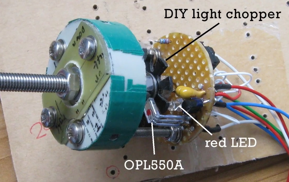
At the heart of the system is the anemometer itself, which makes use of several scavenged parts such as the bottom halves of plastic Easter eggs as wind cups. The cups spin on a short length of M5 threaded rod inside of a 635ZZ bearing, which ultimately rotates a “light chopper” placed between a red LED and a OPL550A optical sensor. In a particularly nice touch, [Richard] has even included a few power resistors arranged around the moving parts to use as a heater which keeps the device from freezing up when the temperature drops. The sensor creates eight digital pulses per revolution, and feeds data into the base station though a 30 meter (98 feet) cable.

From there, the base station uses an ESP8266 to upload wind and temperature data to ThingSpeak and Weather Underground to be viewed through their respective web interfaces and applications. The project really could have ended here and still been impressive in its own right, but the station also includes 433 MHz and NRF24L01 transmitters to send the data to the other display devices which [Richard] has designed.

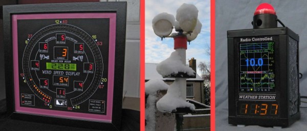
The 433 MHZ display is built into the frame of a lantern, and shows the current time and temperature on an LED readout as well as historical wind and temperature graphs on a 2.2 inch ILI9341 TFT screen which [Richard] has rotated into a portrait layout. There’s a red light on top that blinks whenever a signal is received to show that the system is working, and even a touch sensor which can be used to turn off the TFT screen at a tap if you’re not interested in seeing the full charts.

The other display, which [Richard] calls the “picture frame” utilizes a dizzying array of single LEDs, a handful of digital LED readouts, and even an OLED screen for good measure. They all work together to show the current wind speed as well the averages for the past day in three hour segments. As this display features a real time display of current wind conditions and averages for as short a period of two minutes, it uses the NRF24L01 receiver to get data from the base station at a rate of 3 Hz.

In the past we’ve seen 3D printed weather stations, and of course some pretty simple affairs using little more than an ESP8266 board and some sensors. But few have ever put so much thought into how to present the collected data to the user. If you’re serious about knowing what it’s like outside the confines of your bunker, [Richard] has got some tricks to show you.
Continue reading “An Electronic Love Letter To The Wind”

Building An ESP8266 Doorbell On Hard Mode

It certainly seems as though it should be an easy enough project; all [Miguel De Andrade] wanted was to receive a notification when somebody was pressing his doorbell, and thought it would be a good project to get his feet wet in the wonderful world of ESP8266 hacking. But as fate would have it, not everything went according to plan. In the end he got it sorted out, but it’s an interesting look at how even the “easy” projects can call the gremlins out of hiding.

Arguably, the problems started when [Miguel] picked up an ESP-01 module from a local electronics retailer. While the convenience of buying the hardware in a brick and mortar store can’t be overstated, it did mean he was stuck with a slightly more spartan experience compared to the more common ESP “development boards”. Programming it externally with a Teensy ended up not being much of an obstacle, but it did mean he was stuck with only two GPIO pins.

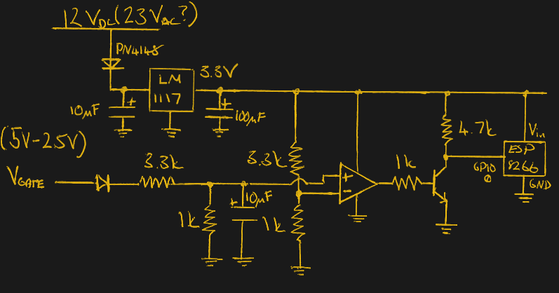
At any rate, with ESP in hand, the next step was figuring out how the existing bell and intercom system even worked. Unfortunately, after some experimentation [Miguel] found there was a bit more going on there than he’d hoped. According to his multimeter, the one line from the intercom sits at approximately 5 VDC when it’s open, and drops down to 2.5 VDC when pressed. If that wasn’t bad enough, picking up the handset to answer the intercom sent the voltage up to a microcontroller-killing 12 VDC. To complicate maters further, the supply line for the intercom was 23 VAC, so he’d need to rectify that somehow if he wanted to avoid a separate power supply for the ESP.

To turn this jumble of voltages into a nice clean 0 – 3.3 V signal for the ESP8266, he came up with a circuit based around the LM358 comparator that utilizes an LM117 regulator to power itself and the ESP at the same time. A couple of diodes are there to block the AC component from causing trouble, and an A2N2222A transistor is used as a buffer amplifier to boost the output of the comparator so it registers as a digital HIGH on the ESP. The circuit took a bit of fiddling to get sorted out, but in the end [Miguel] says it seems to get the job done.

You might think the problems were solved, but this is where it gets really annoying. The system would work fine for awhile, and then inexplicably go silent. In diagnosing the problem he realized that his circuit connected to GPIO_0 was inadvertently putting the ESP8266 into programming mode, since it was holding the pin LOW unless the intercom button was pressed. He assumed he could just move the circuit to the other GPIO pin, but as that one has the board’s LED on it, that caused its own problems. For now, [Miguel] hasn’t come up with a solution to this issue, and has learned to live with the fact that the system won’t come back up cleanly should it lose power for any reason.

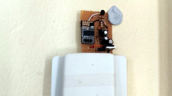
If you’re looking for a slightly classier look than a scrap of perfboard stuck on the wall with what appears to be chewing gum, we’ve also seen the ESP8266 used in some more ornate doorbell setups. Of course if you still haven’t gotten your head wrapped around the whole Internet-connected button thing, you can always start with something a little easier.

The Age Of Hypersonic Weapons Has Begun

With a highly publicized test firing and pledge by President Vladimir Putin that it will soon be deployed to frontline units, Russia’s Avangard hypersonic weapon has officially gone from a secretive development program to an inevitability. The first weapon of its type to enter into active service, it’s capable of delivering a payload to any spot on the planet at speeds up to Mach 27 while remaining effectively unstoppable by conventional missile defense systems because of its incredible speed and enhanced maneuverability compared to traditional intercontinental ballistic missiles (ICBMs).

Rendering of Avangard reentering Earth’s atmosphere

In a statement made after the successful test of Avangard, which saw it hit a target approximately 6,000 kilometers (3,700 miles) from the launch site, President Putin made it clear that the evasive nature of the weapon was not to be underestimated: “The Avangard is invulnerable to intercept by any existing and prospective missile defense means of the potential adversary.” The former Soviet KGB agent turned head of state has never been one to shy away from boastful claims, but in this case it’s not just an exaggeration. While the United States and China have been working on their own hypersonic weapons which should be able to meet the capabilities of Avangard when they eventually come online, there’s still no clear deterrent for this type of weapon.

Earlier in the year, commander of U.S. Strategic Command General John Hyten testified to the Senate Armed Services Committee that the threat of retaliation was the best and perhaps only method of keeping the risk of hypersonic weapons in check: “We don’t have any defense that could deny the employment of such a weapon against us, so our response would be our deterrent force.” Essentially, the threat of hypersonic weapons may usher in a new era of “mutually assured destruction” (MAD), the Cold War era doctrine that kept either side from firing the first shot knowing they would sustain the same or greater damage from their adversary.

With President Putin claiming Avangard has already entered into serial production and will be deployed as soon as early 2019, the race is on for the United States and China to close the hypersonic gap. But exactly how far away is the rest of the world from developing an operational hypersonic weapon? Perhaps more to the point, what does “hypersonic weapon” really mean?

Continue reading “The Age Of Hypersonic Weapons Has Begun”

Raspberry Pi Powers This Retro Chess Computer

If you imagine somebody playing chess against the computer, you’ll likely be visualizing them staring at their monitor in deep thought, mouse in hand, ready to drag their digital pawn into play. That might be accurate for the folks who dabble in the occasional match during their break, but for the real chess aficionados nothing beats playing on a real board with real pieces. Of course, the tricky part is explaining the whole corporeal thing to a piece of software on your computer.

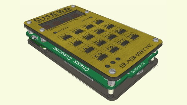
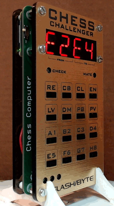
Enter the “Chess Challenger” by [slash/byte]. Modeled after a commercial gadget of the same name from 1978, his retro-themed open hardware design utilizes the Raspberry Pi Zero and modern chess software to bring the vintage concept into the 21st century. With the Chess Challenger and a standard board, the player can face off in an epic battle of wits against the computer without risk of developing carpal tunnel. We can’t guarantee though that a few boards might not get flipped over in frustration.

The pocket sized chess computer uses a “sandwich” style construction which shows off the internals while still keeping things reasonably protected. All of the electronics are housed on the center custom PCB which features a HT16K33 driver for the dual LTP-3784E “starburst” LED displays, a MCP1642B voltage regulator, 16 TL3305 tactile switches for the keyboard, and a MCP73871 battery management chip for the 3.7 volt lithium-ion battery that powers the whole show. The Pi Zero itself connects to the board by way of the GPIO header, and is mechanically supported by the standoffs used to hold the device together.

On the software side of things, the Pi is running the mature Stockfish open source chess engine. In development now for over a decade, this GPL licensed package aims to deliver a world-class chess gameplay on everything from smartphones to desktop computers, and we’ve seen it pop up in a number of projects over the years. [slash/byte] has provided a ready to flash SD card image for the Raspberry Pi, and even provides detailed installation and setup instructions which guide you through some of the more thorny aspects of the setup such as getting the Pi running from a read-only operating system so that abrupt power cuts don’t clobber the filesystem.

Over the years, some of the most impressive projects we’ve seen revolved around playing chess, and this latest entry by [slash/byte] is no exception. Another example of the lengths the chess community will go to perfect the Game of Kings.

Continue reading “Raspberry Pi Powers This Retro Chess Computer”

Underclocking The ESP8266 Leads To WiFi Weirdness

Sometimes the best hacks come from the most basic of questions. In this case, [CNLohr] was wondering what would happen if he started to reduce the clock speed of the ESP8266’s Baseband PLL (BBPLL) while still trying to communicate with it. You know, as one does. The results ended up being fairly surprising, and while it’s not immediately clear if there’s a practical application for this particular trick, it’s certainly worth some additional research.

Code for stepping through clock speeds

The idea here is that the BBPLL is the reference clock for the entire system, including all of the peripherals. So underclocking it doesn’t just slow down code execution as you might expect, but it also slows down the chip’s interactions with the outside world. [CNLohr] demonstrates this concept in the video below, showing how the baud rate used to view the serial output from the ESP8266 needs to be adjusted to match the chip’s frequency or else you’ll only get garbage on the line.

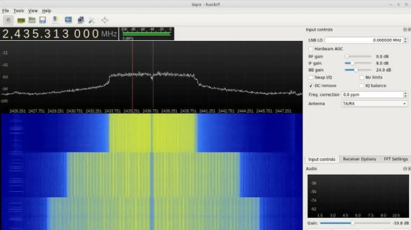
But what happens to the WiFi? As [CNLohr] discovered, while the center frequency itself doesn’t change, the channel width gets narrower as the clock rate is lowered. When viewed on the waterfall display of a software defined radio (SDR), the transmission can be seen “compressing” in a step pattern as the clock rate is reduced. As one might expect, the 802.11 packets become indecipherable to a normal WiFi device running in monitor mode. The signal is still at the correct frequency, but the devices can no longer understand each other.

Now it was time for another of those basic questions. What would happen if you did the same thing to a second ESP8266? Much to his surprise, [CNLohr] discovered that the two devices could still communicate successfully as long as their BBPLL clock speed was the same. From an outsider’s perspective it looked like gibberish, but to the two ESPs which had been slowed by the same amount, everything worked as expected even though the 802.11 standards say it shouldn’t.

So what can you do with this? The most obvious application is a “stealth” WiFi connection between ESP8266s which wouldn’t show up to normal devices, a communications channel invisible to all but the most astute eavesdropper. [CNLohr] has made all the source code to pull this trick off public on GitHub, and it should be interesting to see what kind of applications (if any) hackers find for this standards-breaking behavior.

If your thing is devices being forced into operations they were never intended to by particularly twisted hackers, check out our recent coverage of the USB serial adapter turned SDR by [Ted Yapo].

Continue reading “Underclocking The ESP8266 Leads To WiFi Weirdness”

The Solderdoodle Open Source Iron Rides Again

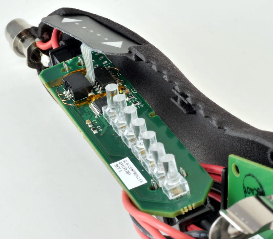
Over the last year or so, cordless portable soldering irons have become all the rage. In fact, at this point a good number of Hackaday readers out there have likely traded in their full-size AC irons for a DC iron that’s only slightly larger than a pen. But before the big boom in portable irons, in the ye olden days of 2014, we brought you word of the open source Solderdoodle created by [Isaac Porras]. Based upon the Weller BP645 and featuring a 3D printed case, the DIY iron was designed to be charged from a standard USB port.

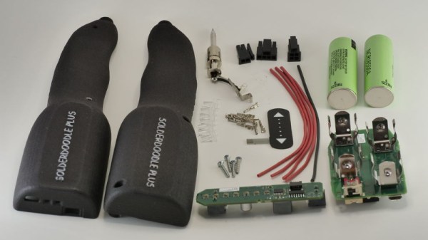
Now, [Isaac] is back with an updated version he calls the Solderdoodle Plus. It’s still based on the heating element from the Weller BP645, but now boasts twice the power, an improved 3D printed case, an intuitive touch-based user interface, and even some LED blinkenlights for good measure. As with the original Solderdoodle the hardware and software for the device are open source and you’re invited to build your own, though kits are also available through an already fully-funded Kickstarter campaign.

[Isaac] says that the temperature control functions on traditional corded soldering irons waste energy due to the large thermal mass they have to bring up to temperature. But with less thermal mass and a system of variable duty cycle pulsed power, he says the Solderdoodle Plus can do the same work as an old-school 60 watt iron while only consuming 10 watts. This allows the iron to maintain a constant 500°C for over an hour on the dual internal Panasonic NCR18500A lithium-ion batteries, and means you can charge it up with nothing more exotic than a micro USB cable.

Continue reading “The Solderdoodle Open Source Iron Rides Again”

A Practical Portable Wii Emerges From The Memes

A few months ago, [Shank] built what will almost certainly go down in history as the world’s smallest portable Nintendo Wii. As it turns out, the Wii motherboard is home to a lot of unnecessary hardware, and with a careful hand and an eye for detail, it’s possible to physically cut it down to a much smaller unit; allowing this particularly tenacious hacker to put an actual Wii, along with everything else required to make it portable, into an Altoids tin.

As you might expect, between the cramped controls, comically short battery life, and the fact that the whole thing got hot to the touch during use, it was a miserable excuse for a portable console. But the incredible response the project received inspired [Shank] to dust off an earlier project: a far more practical portable Wii that he calls PiiWii. This time around the handheld is a more reasonable size, a useful battery life, and proper controls. It even has an integrated “Sensor Bar” so you can use real Wii Remotes with it. It might not be the prettiest portable console conversion we’ve ever seen, but it certainly ranks up there as one of the most complete.

[Shank] actually “finished” the PiiWii some time ago, but in his rush to complete the project he got a little overzealous with the hot glue and ended up with a device that was difficult to diagnose and fix when things started to go wrong. He shelved the project and moved on to his Altoids tin build, which helped him refine his Wii shrinking skills. With a clearer head and some more practical experience under his belt, the PiiWii was revamped and is clearly all the better for it.

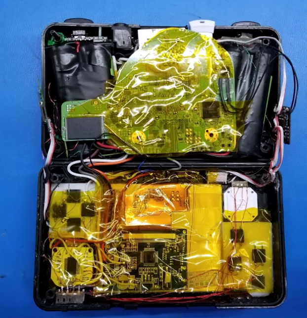
Unlike previous Wii portables we’ve seen, there’s no attempt at adding GameCube controller ports or video out capability. It’s built to be a purely handheld system, and that focus has delivered a system that’s roughly the size of the original Game Boy Advance. Beyond the cleverly sliced Wii motherboard, the inside of the PiiWii features a 3.5 inch display, a custom designed audio amplifier PCB, four 3400 mAh cells which deliver a run time of around four hours, a 3DS “slider” analog stick, and a generous helping of Kapton tape in place of hot glue.

If there’s any criticism of the PiiWii, it’s likely going to be about the system’s boxy exterior. But as [Shank] explains, there’s an excellent reason for that: it’s literally built into a project box. He simply took a commercially available ABS project box, the Polycase SL 57, and made all his openings on the front with a laser cutter. Other than the fact taking a laser to ABS releases hydrogen cyanide, he found it a good way to quickly knock out a custom enclosure.

Last year we took a look his ridiculously small Altoids tin Wii, and while that was an impressive project to be sure, we’re glad he revisited the PiiWii and showed that a portable Wii can be more than just a novelty. Compared to other systems, the Wii doesn’t seem to get the portable treatment that often, so we’re always glad to see somebody come in and do the concept justice.

Continue reading “A Practical Portable Wii Emerges From The Memes”