ESP8266 Home Computer Hides Unexpected Gems

With a BASIC interpreter and free run throughout their hardware, home computers like the ZX Spectrum and Commodore 64 used to be a pervasive way to light that hacker fire. With the advent of cheap single board computers like the Raspberry Pi, devices purpose built to emulate these classic systems have become fairly commonplace. [uli] built a device in this vein called the BASIC Engine which is driven by a microcontroller and a handful of hardware peripherals. Like other examples it can be attached to a keyboard, programmed in a BASIC, play video and sound, etc. But digging into the BASIC Engine reveals that it’s similarity to other devices is only skin deep.

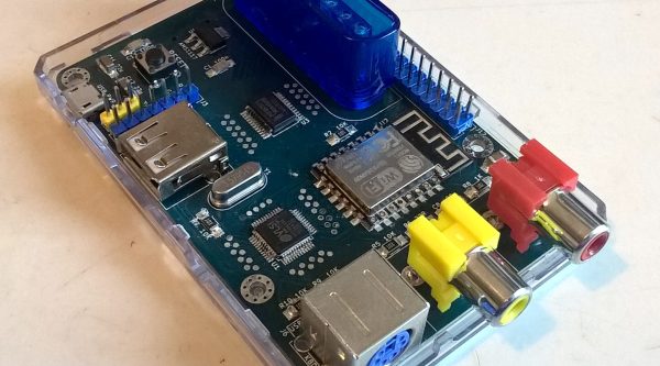
The current version of the BASIC Engine (“rev2”) lives in a Raspberry Pi 3 case for convenience. It has RCA connectors for NTSC or PAL video output and mono audio, plus a bank of headers to tap into GPIOs, connectors for a keyboard, and more. [uli] wanted to aim for extreme low cost so a relatively beefy board like a Raspberry Pi didn’t fit the bill, and we expect it was an enjoyable challenge. Instead its interpreter runs atop an ESP8266 but with the networking stack removed. [uli] was disheartened by how bloated even a “Hello world” program was and ripped it out, discovering that hidden beneath was a very powerful and disproportionately inexpensive general purpose microcontroller. The video is driven by a VS23S010, sold as a 1 Mbit parallel SRAM with a neat trick; it also includes a composite video controller!
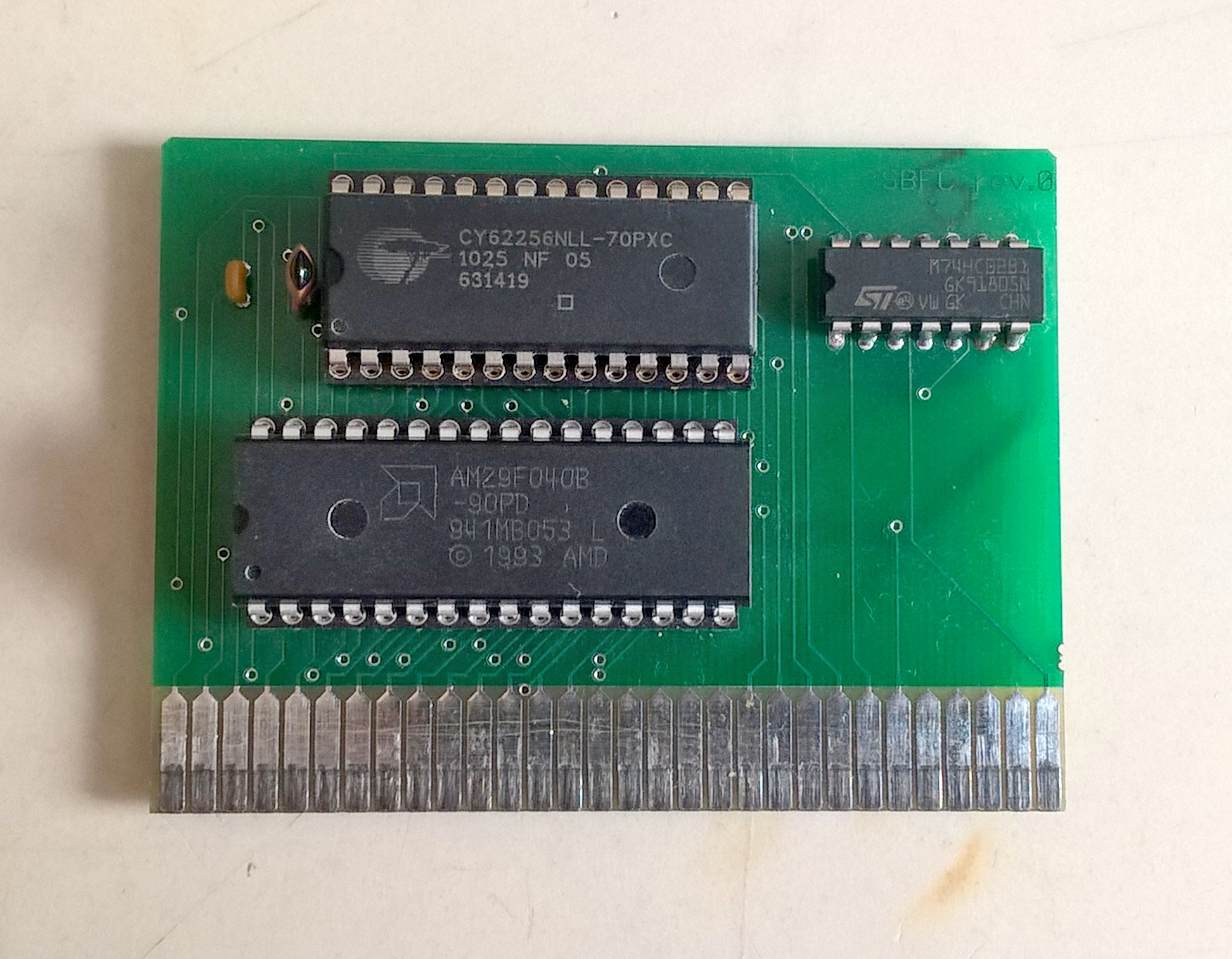
The real treat here is [uli]’s history writeup of how the BASIC Engine came to be. We’d recommend brewing a cup of coffee and sitting down for a full read-through. The first version was inspired by the PlayPower project, which was repurposing clones of Nintendo’s Famicom (NES to Americans) game console to make low cost home computers, complete with keyboard and gamepad input. [uli] started out by building a custom cartridge for a particular Famicom clone that ran a BASIC interpreter but after showing it to disinterested adults the project was left fallow. Years later, [uli] was encouraged to pick up the project again, leading down a twisted rabbit hole to where we are today.

If you want to build a BASIC Engine for yourself, Gerbers and build instructions are available on the pages linked above.

Thanks for the tip [antibyte]!
TL084 die blocks

Ken Shirriff Found Butterflies In His Op-Amp

In 1976, Texas Instruments came out with the TL084, a four JFET op-amp IC each with similar circuitry to Fairchild’s very popular single op-amp 741. But even though the 741 has been covered in detailed, when [Ken Shirriff] focused his microscope on a TL084, he found some very interesting things.

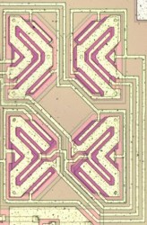
JFETs on the TL084 op-amp

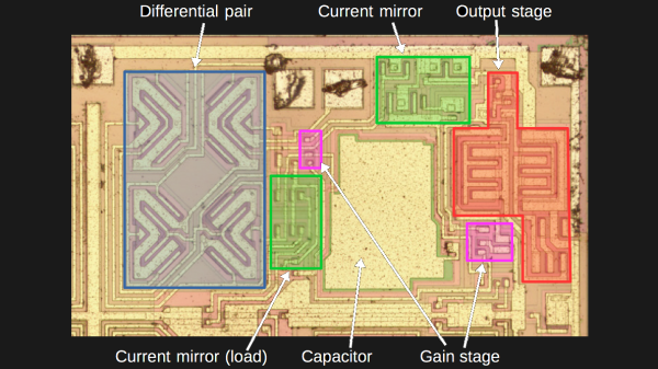
To avoid using acid to get at the die, he instead found a ceramic packaged TL084 and pried off the cover. The first things he saw were four stabilizing capacitors, by far the largest structures on the die and visible to the naked eye.

When he peered into his microscope he next saw butterfly shapes which turned out to be pairs of input JFETs. The wide strips are the gates and the narrower strip surrounded by each gate is the source. The drain is the narrow strip surrounding each gate. Why arrange four JFETs like this? It’s possible to have temperature gradients in the IC, one side being hotter than the other. These gradients can affect the JFET’s characteristics, unbalancing the inputs. Look closely at the way the JFETs are connected and you’ll see that the top-left one is connected to the bottom-right one, and similarly for the other two. This diagonal cross-connecting cancels out any negative effects.

[Ken’s] analysis in his article doesn’t stop there though. Not only does he talk more about these JFETs but he goes over the rest of the die too. It’s well worth the read, as is his write-up about the 741 which we’ve also covered.

Roll Your Own Trackball Mouse

What do you do when you’re into trackball mice, but nothing out there is affordable or meets all your murine needs? You build one, of course. And if you’re like [Dangerously Explosive], who has a bunch of old optical mice squeaking around the shop, you can mix and match them to build the perfect one.

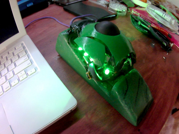
The mouse, which looks frozen mid-transformation into a rodential assassin, is a customized work of utilitarian art. Despite the excellent results, this project was not without its traps. [Dangerously] got really far into the build before discovering the USB interface chip was dead. Then he tried to sculpt a base out of Plasticine and discovered he’d bought the one kind of clay that can’t be baked. After trying his hand at making homemade salt dough, he painstakingly whittled a base from scrap pine using a drill and a hacksaw.

Every bit of this mouse is made from recycled bits, which, if you pair that with the paint job and the chosen shade of blinkenlights, makes this a green mouse on three levels. One of the two parts of this mouse that isn’t literally green, the cord, is still ecologically sound. [Dangerously] wanted a really long tail, so he scavenged a charger cable built for fruity hardware and threaded it through a hollowed-out piece of purple paracord.

We love the thumb-adjacent scroll wheel and the trackball itself, which is a ping pong ball painted black. The cool part is the guide it rolls around in. [Dangerously] spent a long time hand-whittling the perfect size hole in a particularly wide mouse palm rest. All that plastic shaving paid off, because the action is smooth as Velveeta.

[Dangerously] certainly designed this mouse to fit his preferences, and ergonomics seem a bit secondary. For a truly custom fit, try using whatever passes for Floam these days.

Beats An Extension Cord

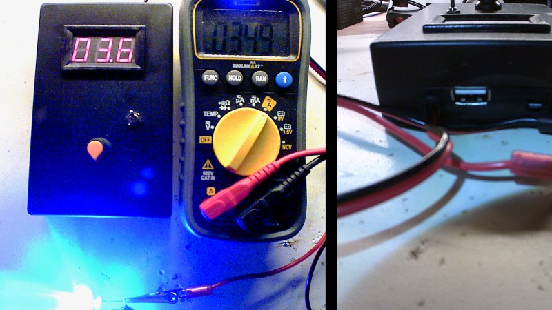
What does your benchtop power supply have that [Pete Marchetto]’s does not? Answer: an extension cord draped across the floor. How often have you said to yourself, “I just need to energize this doodad for a couple seconds,” then you start daisy chaining every battery in the junk drawer to reach the necessary voltage? It is not uncommon to see battery packs with a single voltage output, but [Pete] could not find an adjustable one, so he built his own and put it on Tindie.

Presumably, the internals are not going to surprise anyone: an 18650 battery, charging circuit, a voltage converter, display, adjustment knob, and a dedicated USB charging port. The complexity is not what intrigues us, it is the fact that we do not see more of them and still wind up taping nine-volt batteries together. [Editor’s note: we use one made from an old laptop battery.]

This should not replace your benchtop power supply, it does not have the bells and whistles, like current regulation, but a mobile source of arbitrary voltage does most of the job most of the time. And it’s what this build hasn’t got (a cord) that makes it most useful.

This Is The Year Conference Badges Get Their Own Badges

Over the last few years, the art and artistry of printed circuit boards has moved from business cards to the most desirable of all disposable electronics. I speak, of course, of badgelife. This is the community built on creating and distributing independent electronic conference badges at the various tech and security conferences around the globe.

Until now, badgelife has been a loose confederation of badgemakers and distributors outdoing themselves each year with ever more impressive boards, techniques, and always more blinky bling. The field is advancing so fast there is no comparison to what was being done in years past; where a simple PCB and blinking LED would have sufficed a decade ago, now we have customized microcontrollers direct from the factory, fancy new chips, and the greatest art you’ve ever seen.

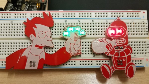
Now we have reached a threshold. The badgelife community has gotten so big, the badges are getting their own badges. This is the year of the badge add-on. We’re all building tiny trinkets for our badges, and this time, they’ll all work together. We’re exactly one year away from a sweet Voltron robot made of badges.

Continue reading “This Is The Year Conference Badges Get Their Own Badges” →

Cheap Front Panels With Dibond Aluminium

The production capability available to the individual hacker today is really quite incredible. Even a low-end laser engraver can etch your PCBs, and it doesn’t take a top of the line 3D printer to knock out a nice looking enclosure. With the wide availability of these (relatively) cheap machines, the home builder can churn out a very impressive one-off device on a fairly meager budget. Even low volume production isn’t entirely out of the question. But there’s still one element to a professional looking device that remains frustratingly difficult: a good looking front panel.

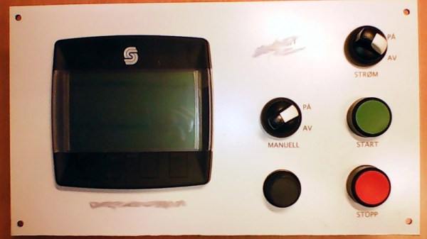
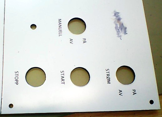
Now if your laser is strong enough to engrave (and ideally cut) aluminum sheets, then you’ve largely solved this problem. But for those of us who are plodding along with a cheap imported diode laser, getting text and images onto a piece of metal can be rather tricky. On Hackaday.io, [oaox] has demonstrated a cost effective way to create metal front panels for your devices using a print service that offers Dibond aluminum. Consisting of two thin layers of aluminum with a solid polyethylene core, this composite material was designed specifically for signage. Through various online services, you can have whatever you wish printed on a sheet of pre-cut Dibond without spending a lot of money.

As explained by [oaox], the first step is putting together the image you’ll send off to the printer using a software package like Inkscape. The key is to properly define the size of the Dibond plate in your software and work within those confines, otherwise the layout might not look how you expected once the finish piece gets back to you. It’s also important to avoid lossy compression formats like JPEG when sending the file out for production, as it can turn text into a mushy mess.

When you get the sheet back, all you need to do is put your holes in it. Thanks to the plastic core, Dibond is fairly easy to cut and drill as long as you take your time. [oaox] used a step drill for the holes, and a small coping saw for the larger openings. The final result looks great, and required very little effort in the grand scheme of things.

But how much does it cost? Looking around online, we were quoted prices as low as $7 USD to do a full-color 4×4 inch Dibond panel, and one site offered a 12×12 panel for $20. For a small production run, you could fit several copies of the graphics onto one larger panel and cut them out with a bandsaw; that could drop the per-unit price to only a couple bucks.

We’ve seen some clever attempts at professional looking front panels, from inkjet printing on transparencies to taking the nuclear option and laser cutting thin plywood. This is one of those issues the community has been struggling with for years, but at least it looks like we’re finally getting some decent options.

Silicon Bugs In The FTDI FT232R, And A Tidy RF VCO Project

[Scott Harden] wrote in to tell us of some success he’s having using the FT232 chip to speak SPI directly from his laptop to a AD98850 digital signal generator. At least that was his destination. But as so often in life, more than half the fun was getting there, finding some still-unsolved silicon bugs, and (after simply swapping chips for one that works) potting it with hot glue, putting it in a nice box, and putting it up on the shelf.

In principle, the FTDI FT232 series of chips has a bit-bang mode that allows you to control the individual pins from a fairly simple API on your target computer, using their drivers and without installing anything on basically any platform. We wrote this feature up way back in 2009, and [Scott] was asking himself why he doesn’t see more hacks taking advantage of bit-bang mode.

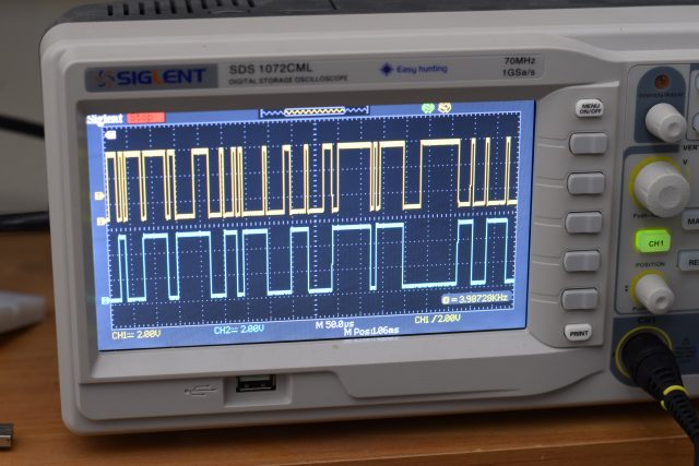
“Square” waves

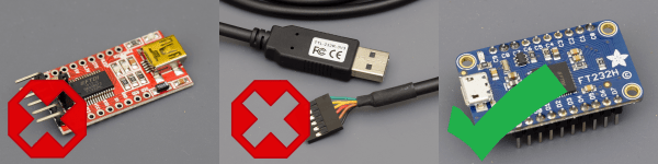
Then he answered his own question the hard way, by spending hours “debugging” his code until he stumbled on the FTDI errata note (PDF), where they admit that bit-bang mode doesn’t get timings right at all on the FT232R and FT232RL parts. FTDI has made claims that they fixed the bug in subsequent chip revisions, but the community has not been able to confirm it. If you want to use bit-bang mode, which is plenty cool, steer clear of the FT232R chips — the ones found in the ever-popular FTDI cables and many adapter dongles.

The good news here is twofold. First, now you know. Second, bit-bang mode is tremendously useful and it works with other chips from the vendor. Particularly, the FT232H and FT230X chips work just fine, among others. And [Scott] got his command-line controlled digital VCO up and running. All’s well that ends well?

We’ll wrap up with questions for the comment section. Do other manufacturers’ cheap USB-serial chips have an easily accessible bit-bang mode? Are any of you using USB bit-bang anyway? If so, what for?