SMD Breadboard Adaptors Skip Schematic, Goes Straight To PCB

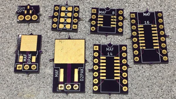
If you need to add one or two SMT chips to your breadboarded prototype, [Travis Hein] has you covered. He designed a set of small SMD adaptor boards for various SOIC, SOT23, and DPAC patterns using KiCad.  He has released them as open source, so you can feel free to use them or modify them as needed.

Normally we don’t see people bypassing the schematics when designing a PCB. But we can agree that [Travis] has found a situation where going direct to PCB makes more sense. He just plops down the package in Pcbnew, adds some pin headers and wires everything up directly on the PCB. (But don’t worry, some of you may remember [Travis] from his earlier SSR mains switching project, which demonstrates that he can indeed draw proper schematics.) We know there are more people out there who prefer to go straight to PCB layout… [mikeselectricstuff] comes to mind. If you could yourself among this tribe, let use know your reasoning in the comments below.

We wrote about a similar universal breakout boards for SMD parts back in 2016, which is a single breakout board for two- and three-pin jelly-bean components. If you paired some of those boards with [Travis]’s breakout boards, it would make a great combination to keep in your prototyping gadgets bin. Consider this project the next time your favorite PCB shop has a sale.

USB Adaptor Isolates Multiple Serial Interfaces

You need a Swiss Army knife of serial communications? Ollie is a compact isolated USB adaptor that provides USB, CAN bus, and two UARTs at logic, RS-232, and RS-485 signaling levels, as well as an isolated power supply.  [Slimelec] has managed to squeeze all this into a package the size of a harmonica.  We like the technique of making the enclosure from PCB material, complete with clearly labeled switch, LED and connector pinout names.

So far, only the compiled firmware is available for this project, but hardware files, and presumably the source code and documentation, are coming soon.

The central themes here are  isolation and flexibility. We can’t find the isolation voltage in the project specifications, but the CANable project on which this adaptor is based provides 2.5 kV galvanic isolation.  A single isolated USB interface is also provided over a standard Type A connector. The four-wire logic-level UART signals are available on a 2 x 7 box header, and are voltage selectable.  The RS-232, RS-485, and CAN signals are on an 8-pin pluggable screw terminal block, or you can use a DB9 connector with a pluggable adaptor board.

Whether you need a troubleshooting aid for field testing, are using CAN bus on your projects, or just want to isolate your expensive computer from sketchy prototype hardware, have a look at this project.

A Breadboard Block For 8-Bit CPUs

Breadboard CPUs are a fantastic learning experience and require serious dedication and patience. Occasionally, CPU builders eschew their breadboards and fab their design onto a PCB. But this takes away the flexibility and some of the opportunity for learning that breadboard CPUs offer. [c0pperdragon] was doing the same sort of repetitive wiring from project to project as most 8-bit breadboard CPUs use memory, a bus, an IO controller, ROM, and a few other passive components.

Taking a compromise approach, [c0pperdragon] built a PCB that can be used as a building block in his custom CPUs which they have titled “ByteMachine”. A single row of 34 pins offer power, clock, reset, 19 address bus lines, 8 data bus lines, and a ROM selector. This means that the CPUs can fit on a single breadboard and can run faster as the impedance of the breadboard has less effect on the circuit. With 512 KB of RAM and 512 KB of ROM, in a ZIF socket for easy reprogramming, ByteMachine has plenty of space.

One drawback is the lack of IO. There is no dedicated address space as this would require decoding logic between the RAM and the CPU. [C0pperdragon] added a simple 8-bit output register provided by a 74-series logic IC. The data is displayed on 8 red LEDs and can be accessed via pins. Input is accomplished in a similar way with just 8 bits of digital input provided.

[C0pperdragon] has built the 65C02, 65C816Z84C00, and the i8088 with the ByteMachine. Each was documented with incredible schematics, pictures, and test programs on GitHub. Next time you’re looking to build a CPU on a breadboard, maybe start with a ByteMachine. In some ways, it might improve your learning experience as it makes the incredible mass of wires we’ve seen on other projects a tad more manageable.

Thanks [Reinhard Grafl] for sending this one in!

Inputs Of Interest: The OrbiTouch Keyless Keyboard And Mouse

I can’t remember how exactly I came across the OrbiTouch keyboard, but it’s been on my list to clack about for a long time. Launched in 2003, the OrbiTouch is a keyboard and mouse in one. It’s designed for people who can’t keyboard regularly, or simply want a different kind of experience.

The OrbiTouch was conceived of by a PhD student who started to experience carpal tunnel while writing papers. He spent fifteen years developing the OrbiTouch and found that it could assist many people who have various upper body deficiencies. So, how does it work?

It’s Like Playing Air Hockey with Both Hands

To use this keyboard, you put both hands on the sliders and move them around. They are identical eight-way joysticks or D-pads, essentially. The grips sort of resemble a mouse and have what looks like a special resting place for your pinky.

One slider points to groups of letters, numbers, and special characters, and the other chooses a color from a special OrbiTouch rainbow. Pink includes things like parentheses and their cousins along with tilde, colon and semi-colon. Black is for the modifiers like Tab, Alt, Ctrl, Shift, and Backspace. These special characters and modifiers aren’t shown on the hieroglyphs slider, you just have to keep the guide handy until you memorize the placement of everything around the circle.

You’re gonna need a decent amount of desk space for this. Image via OrbiTouch

The alphabet is divided up into groups of five letters which are color-coded in rainbow order that starts with orange, because red is reserved for the F keys. So for instance, A is orange, B is yellow, C is green, D is blue, E is purple, then it starts back over with F at orange. If you wanted to type cab, for instance, you would start by moving the hieroglyph slider to the first alphabet group and the color slider to green.

Continue reading “Inputs Of Interest: The OrbiTouch Keyless Keyboard And Mouse”

Improved Part Searches For JLCPCB Parts

Finding the JLCPCB component parts library frustrating to navigate, [Jan Mrázek] took matters into his own hands and made an open-source parametric search utility. We’ve all probably wasted time before trying to track down a particular flavor of a part, and this tool promises to make the process easier.  It downloads data from the JLCPCB parts site upon initialization and presents the user with typical selection filters for categories and parameter values. You can install it yourself on GitHub Pages, or [Jan] provides a link to his site.

For the curious, the details of how to pull parts information from the JLBPCB site can be found in the project’s source code.  We like it when a distributor provides this level of access to their part details and parameters, allowing others to sort and filter the parts in ways not originally envisioned by the site design team.  We think this is a win-win situation — distributors can’t sell parts that designers can’t find.

If [Jan]’s name sounds familiar, it should be.  We have written about several of his projects before, two of them are also PCB designer tools ( KiCad Board Renderings and KiCad Panelization ).

Current Sensor Makes Intriguing Use Of Concrete

Getting a product to market isn’t all about making sure that the product does what it’s supposed to. Granted, most of us will spend most of our time focusing on the functionality of our projects and less on the form, fit, or finish of the final product, especially for one-off builds that won’t get replicated. For those builds that do eventually leave the prototyping phase, though, a lot more effort goes into the final design and “feel” of the product than we might otherwise think. For example, this current sensor improves its feel by making use of cast concrete in its case.

The current sensor in this build is not too much out of the ordinary. [kevarek] built the sensor around the MCA1101-50-3 chip and added some extra features to improve its electrostatic discharge resistance and also to improve its electromagnetic compatibility over and above the recommended datasheet specifications. The custom case is where this one small detail popped out at us that we haven’t really seen much of before, though. [kevarek] mixed up a small batch of concrete to pour into the case simply because it feels better to have a weightier final product.

While he doesn’t mention building this current sensor to sell to a wider audience, this is exactly something that a final marketable product might have within itself to improve the way the device feels. Heavier things are associated, perhaps subconsciously, with higher quality, and since PCBs and plastic casings don’t weigh much on their own many manufacturers will add dummy weights to improve the relationship between weight and quality. Even though this modification is entirely separate from the function of the product, it’s not uncommon for small changes in design to have a measurable impact on performance, even when the original product remains unmodified.

Thanks to [Saabman] for the tip!

The Prusa I3 MK3S And A Tale Of Two Sensors

When the Prusa i3 MK3 was released in 2017, it was marketed as being “bloody smart” thanks to the impressive number of sensors that had been packed into the printer. The update wasn’t really about improving print quality over the MK2, but rather to make the machine easier to use and more reliable. There was a system for resuming prints that had stopped during a power outage, a thermometer so the firmware could compensate against thermal drift in the inductive bed sensor, RPM detection on all of the cooling fans, and advanced Trinamic stepper drivers that could detect when the printer had slipped or gotten stuck.

The optical filament sensor of the Prusa i3 MK3.

But the most exciting upgrade of all was the new filament sensor. Using an optical encoder similar to what you’d find in a mouse, the Prusa i3 MK3 could detect when filament had been inserted into the extruder. This allowed the firmware to pause the print if the filament had run out, a feature that before this point was largely unheard of on consumer-grade desktop 3D printers. More than that, the optical encoder could also detect whether or not the filament was actually moving through the extruder.

In theory, this meant the MK3 could sense problems such as a jammed extruder or a tangle in the filament path that was keeping the spool from unrolling. Any other consumer 3D printer on the market would simply continue merrily along, not realizing that it wasn’t actually extruding any plastic. But the MK3 would be able to see that the filament had stalled and alert the user. The capabilities of the optical filament sensor represented a minor revolution in desktop 3D printing, and combined with the rest of the instrumentation in the MK3, promised to all but eradicate the heartbreak of failed prints.

Fast forward to February of 2019, and the announcement of the Prusa i3 MK3S. This relatively minor refresh of the printer collected up all the incremental tweaks that had been made during the production of the MK3, and didn’t really add any new features. Though it did delete one: the MK3S removed the optical encoder sensor used in the MK3, and with it the ability to sense filament movement. Users would have to decide if keeping the ability to detect clogs and tangles was worth giving up all of the other improvements offered by the update.

But why? What happened in those three years that made Prusa Research decide to abandon what promised to be a huge usability improvement for their flagship product? The answer is an interesting look at how even the cleverest of engineering solutions don’t always work as expected in the real-world.

Continue reading “The Prusa I3 MK3S And A Tale Of Two Sensors”