Pushbutton → Push Notification

How many mundane devices upgrade to IoT because they let you monitor a single data point or a variable? That little nudge over the communication precipice allows you to charge 500% more. Now, if you are as handy as a Hackaday reader, you can throw a lazy afternoon at the problem and get the same effect from a “dumb” appliance. If IoT is as simple as getting a notification when your laundry is dry, or your water is boiling, all you really need is a WiFi device and a push notification, right? Does it need to be more complicated than that? [Gianni] believes it is that simple (machine translation) and has built up an easy-to-implement version on Raspberry Pi, Arduino, and ESP8266.

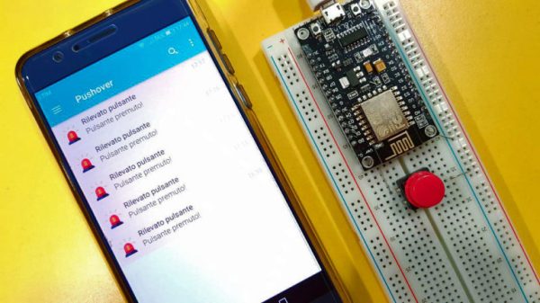
[Gianni] leverages the aptly named Pushover (a paid app with a 1-week trial period) to convert your bits, bytes, words, or strings to a push notification. This idea is born of the desire for a home security system which doesn’t require constant monitoring but instead alerts you to problems. The minimum requirement you need is for your phone to chime with a notification saying, “Your front window sensor has been tripped.” Now it is time to launch your IP camera app or call someone nearby.

It’s not revolutionary, it may be the “Hello World” of IoT, but that is all some people need. The general idea is the same no matter the framework you want to use. For instance, if you Google Suite account, you can set up a chatroom just for your alert notifications; Google’s quickstart takes about 3 minutes to test it out in Python. The same setup is also available for Slack, and [Tom Nardi] did a guide for doing this with Discord. These tackle the receiving side, but the sending side is really flexible too — that MQTT broker you built could easily be the source of the alerts.

Build a handful of these in a weekend and keep them nearby to step up your next project to IoT status with a couple of solder joints. Maybe it will be a motion sensor for your own security system.

Laser Harp Sounds Real Thanks To Karplus-Strong Wave Equation

The harp is an ancient instrument, but in its current form, it seems so unwieldy that it’s a wonder that anyone ever learns to play it. It’s one thing to tote a rented trumpet or clarinet home from school to practice, but a concert harp is a real pain to transport safely. The image below is unrelated to the laser harp project, but proves that portable harping is begging for some good hacks.

Concert grand harps are so big there’s special equipment to move them around. This thing’s called the HarpCaddy

Enter this laser harp, another semester project from [Bruce Land]’s microcontroller course at Cornell. By replacing strings with lasers aimed at phototransistors, [Glenna] and [Alex] were able to create a more manageable instrument that can be played in a similar manner. The “strings” are “plucked” with the fingers, which blocks the laser light and creates the notes.

But these aren’t just any old microcontroller-generated sounds. Rather than simply generating a tone or controlling a synthesizer, the PIC32 uses the Karplus-Strong algorithm to model the vibration of a plucked string. The result is very realistic, with all the harmonics you’d expect to hear from a plucked string. [Alex] does a decent job putting the harp through its paces in the video below, and the write-up is top notch too.

Unique musical instruments like laser harps are far from unknown around these parts. We’ve seen a few that look something like a traditional harp and one that needs laser goggle to play safely, but this one actually looks and sounds like the real thing. Continue reading “Laser Harp Sounds Real Thanks To Karplus-Strong Wave Equation”

A Different Kind Of Hand Controlled Vehicle

It’s generally understood that most vehicles that humans interact with on a daily basis are used with some kind of hand controlled interface. However, this build from [Avisha Kumar]  and [Leul Tesfaye] showcases a rather different take. A single motion input provides both steer and foward/reverse throttle control.

The hand controller lives on a protoboard for ease of testing.

The project consists of a small car, driven with electric motors at the rear, with a servo-controlled caster at the front for steering. Controlled is provided through PIC32 microcontroller receiving signals via Bluetooth. The car is commanded with a hand controller, quite literally — consisting of an accelerometer measuring pitch and roll position of the user’s hand. By tilting the hand left and right affects steering, while the hand is rotated fore and aft for throttle control. Video after the break.

The project was built for a course at Cornell University, and thus is particularly well documented. It provides a nice example of reading sensor inputs and transmitting/receiving data. The actually microcontroller used is less important than the basic demonstration of “Hello World” with robotics concepts. Keep this one in your back pocket for the next time you want to take a new chip for a spin!

We’ve seen similar work before, with a handmade controller using just potentiometers and weights. Continue reading “A Different Kind Of Hand Controlled Vehicle”

Skeletal Robot Skips The Chassis

With the high availability of low-cost modular electronic components, building your own little robot buddy is easier and more affordable than ever. But while the electronics might be dirt cheap thanks to the economies of scale, modular robot chassis can be surprisingly expensive. If you’ve got a 3D printer you can always make a chassis that way, but what if you’re looking for something a bit more artisanal?

For his entry into the Circuit Sculpture Contest, [Robson Couto] has built a simple robot which dumps the traditional chassis for a frame made out of bent and soldered copper wire. Not only does this happen to look really cool in a Steampunk kind of way, it’s also a very cheap way of knocking together a basic bot with just the parts you have on hand. Not exactly a heavy-duty chassis, to be sure, but certainly robust enough to rove around your workbench.

The dual servos constrained within the wire frame have been modified for continuous rotation, which combined with the narrow track should make for a fairly maneuverable little bot. [Robson] equipped his servos with copper wheels built in the same style of the frame, which likely isn’t great for traction but really does help sell the overall look. If you aren’t planning on entering your creation into a contest that focuses on unique construction, we’d suggest some more traditional wheels for best results.

The brains of this bot are provided by an ATmega8 with external 16MHz crystal tacked onto the pins. There’s also a ultrasonic sensor board mounted to the servos which eventually will give this little fellow the ability to avoid obstacles. Of course, it doesn’t take a robotics expert to realize there’s currently no onboard power supply in the design. We’d love to say that he’s planning on using the copper loops of the frame to power the thing via induction, but we imagine [Robson] is still fiddling around with the best way to get juice into his wireframe creation before the Contest deadline.

Speaking of which, there’s still plenty of time to get your own Circuit Sculpture creation submitted. If it’s a functional device that isn’t scared to show off the goods, we’re interested in seeing it. Just document the project on Hackaday.io and submit it to the contest before the January 8th, 2019 deadline.

How A Microcontroller Hiding In A USB Port Became An FPGA Hiding In The Same

When you think of microcontroller development, you probably picture either a breadboard with a chip or a USB-connected circuit board. But Tim Ansell pictured an ARM dev board that is almost completely hidden inside of a USB port. His talk at the 2018 Hackaday Superconference tells that story and then some. Check out the newly published video, along with more details of the talk, after the break.

Continue reading “How A Microcontroller Hiding In A USB Port Became An FPGA Hiding In The Same”

Microcontroller And IMU Team Up For Simple Flight Sim Controls

Classes are over at Cornell, and that means one thing: the students in [Bruce Land]’s microcontroller design course have submitted their final projects, many of which, like this flight control system for Google Earth’s flight simulator, find their way to the Hackaday tips line.

We actually got this tip several days ago, but since it revealed to us the previously unknown fact that Google Earth has a flight simulator mode, we’ve been somewhat distracted. Normally controlled by mouse and keyboard, [Sheila Balu] decided to give the sim a full set of flight controls to make it more realistic. The controls consist of a joystick with throttle, rudder pedals, and a small control panel with random switches. The whole thing is built of cardboard to keep costs down and to make the system easy to replicate. Interestingly, the joystick does not have the usual gimbals-mounted potentiometers to detect pitch and roll; rather, an IMU mounted on the top of the stick provides data on the stick position. All the controls talk to a PIC32, which sends the inputs over a serial cable to a Python script on the PC running Google Earth; the script simulates the mouse and keyboard commands needed to fly the sim. The video below shows [Sheila] taking an F-16 out for a spin, but despite being a pilot herself since age 16, she was curiously unable to land the fighter jet safely in a suburban neighborhood.

[Bruce]’s course looks like a blast, and [Sheila] clearly enjoyed it. We’re looking forward to the project dump, which last year included this billy-goat balancing Stewart platform, and a robotic ice cream topping applicator.

Continue reading “Microcontroller And IMU Team Up For Simple Flight Sim Controls”

A Perfectly Orderly Way To Manage Your Time

[Paul Gallagher] has spent years separating his tasks into carefully measured out blocks, a method of time management known as the Pomodoro Technique. If that’s not enough proof that he’s considerably more organized and structured than the average hacker, you only need to take a look at this gorgeous Pomodoro Timer he’s entered into the Circuit Sculpture Contest. Just don’t be surprised if you suddenly feel like your own time management skills aren’t cutting it.

While [Paul] has traditionally just kept mental note of the hour-long blocks of time he breaks his work into, he thought it was about time he put together a dedicated timer to make sure he’s running on schedule. Of course he could have used a commercially available timer or an application on his phone, but he wanted to make something that was simple and didn’t cause any distractions. A timer that was easy to start, reliable, and didn’t do anything extraneous. We’re not sure if looking like the product of a more advanced civilization was part of his official list of goals, but he managed to achieve it in any event.

The timer is broken up into two principle parts: the lower section which has the controls, USB port, a handful of passive components, and an ATmega328 microcontroller, and the top section which makes up the three digit LED display. The two sections are connected by a header on the rear side which makes it easy for [Paul] to take the timer apart if he needs to get back into it for any reason. Notably absent in the design is a RTC; the relatively short duration of the timer (up to a maximum of 95 minutes) means the ATmega328 can be trusted to keep track of the elapsed time itself with an acceptable amount of drift.

The display side of the timer is really a sight to behold, with the legs of each LED soldered to a pair of carefully bent copper wires so they match the angle of the front panel. The associated resistors have been artfully snipped so that their bodies sit flat on the PCB while their leads reach out to the perfect length. It looks like a maintenance nightmare in there, but we love it anyway.

As we near the half-way mark of the Circuit Sculpture Contest, there’s still plenty of time to submit your own piece of functional art. If you’ve got a project that eschews the printed circuit board for a chance to bare it all, write it up on Hackaday.io and be sure to send it in before the January 8th, 2019 deadline.

Continue reading “A Perfectly Orderly Way To Manage Your Time”