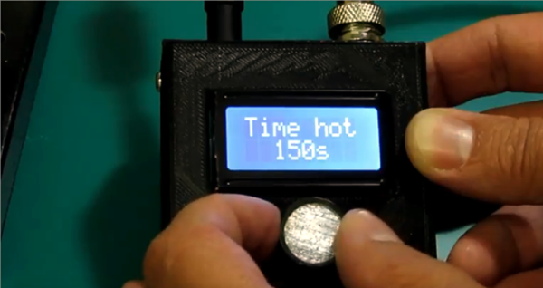
We don’t know if [Marius Taciuc] was thinking about how all Jedi make their own lightsabers as a rite of passage, but he decided that it was time to build his own soldering iron. He used a Hakko T12 tip which has a built-in thermocouple. However, he found that the information on the Internet about the tips was either incomplete or incorrect. Naturally, he figured it out and you can see the completed iron in the video, below.
The problem stems from the thermocouple type. Some sites he found identified it as a type K device. Others said it wasn’t, but didn’t say what kind it was. He took a container of oil and heated it to various temperatures and then measured it with both a commercial soldering iron and the T12 tip. By plotting the data against known thermocouple curves, he concluded the device was actually type C.
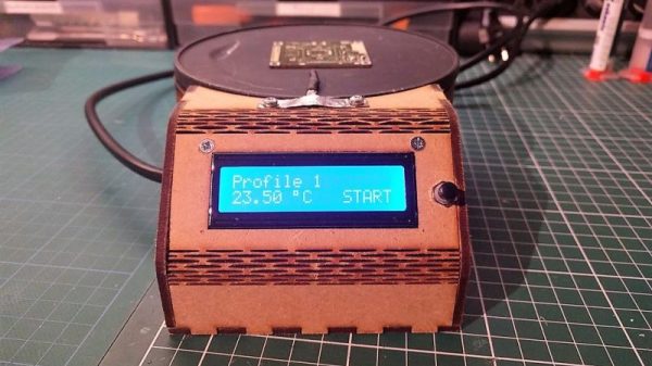
For a DIY reflow setup, most people seem to rely on the trusty thrift store toaster oven as a platform to hack. But there’s something to be said for heating the PCB directly rather than heating the surrounding air, and for that one can cruise the yard sales looking for a hot plate to convert. But an electric wok as a reflow hotplate? Sure, why not?
At the end of the day [ThomasVDD]’s reflow wok is the same as any other reflow build. It has a heat source that can be controlled easily, temperature sensors, and a microcontroller that can run the proportional-integral-derivative (PID) control algorithm needed for precise temperature control. That the heating element he used came from an electric wok was just a happy accident. A laser-cut MDF case complete with kerf-bent joints holds the heating element, the solid-state relay, and the Arduino Nano that runs the show. A MAX6675 thermocouple amp senses the temperature and allows the Nano to cycle the temperature through different profiles for different solders. It’s compact, simple, and [ThomasVDD] now has a spare wok to use on the stove top. What’s not to like?
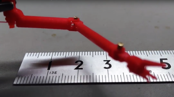
[Nixie] wants to make semiconductors at home, and that requires some unusual tools. Chief among them is a vacuum chamber to perform thin-film deposition, and true to the hacker credo his is homemade, and will soon be equipped with a tiny manipulator arm with magnetically coupled mechanical controls.
If [Nixie]’s setup looks familiar, it might be because we featured his plasma experiments a few days ago. He was a little cagey then about his goal, but he’s come clean with his desire to make his own FETs (a project that is his 2018 Hackaday Prize entry). Doing so will require not only creating stable plasmas, but also the ability to move substrates around inside the vacuum chamber. Taking inspiration from the slender and maneuverable instruments surgeons use for laparoscopic procedures, [Nixie] is working on a miniature arm that will work inside his vacuum chamber. The video below is a 3D-printed proof-of-concept model in action, and shows how the arm’s segments will be controlled by cables. What’s really interesting is that the control cables will not penetrate the vacuum chamber — they’ll be moved right through the glass wall using magnets.
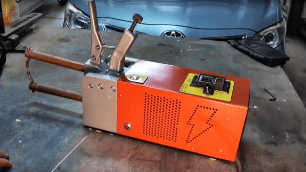
Even when you build something really, really nice, there’s always room for improvement, right? As it turns out for this attempted upgrade to a DIY spot welder, not so much.
You’ll no doubt recall [Mark Presling]’s remarkably polished and professional spot welder build that we featured some time ago. It’s a beauty, with a lot of thought and effort put into not only the fit and finish but the function as well. Still, [Mark] was not satisfied; he felt that the welder was a little underpowered, and the rewound microwave oven transformer was too noisy. Taking inspiration from an old industrial spot welder, he decided to rebuild the transformer by swapping the double loop of battery cable typically used as a secondary with a single loop of thick copper stock. Lacking the proper sized bar, though, he laminated multiple thin copper sheets together before forming the loop. On paper, the new secondary’s higher cross-sectional area should carry more current, but in practice, he saw no difference in the weld current or his results. It wasn’t all bad news, though — the welder is nearly silent now, and the replaced secondary windings were probably a safety issue anyway, since the cable insulation had started to melt.
Given [Mark]’s obvious attention to detail, we have no doubt he’ll be tackling this again, and that he’ll eventually solve the problem. What suggestions would you make? Where did the upgrade go wrong? Was it the use of a laminated secondary rather than solid bar stock? Or perhaps this is the best this MOT can do? Sound off in the comments section.
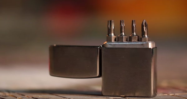
[Laura Kampf] found a new use for an old Zippo lighter by turning it into a carrier for her screwdriver bits. There are several multitools out there which can accept standard screwdriver bits. The problem is carrying those bits around. Leaving a few bits in your pocket is a recipe for pocket holes and missing bits.
[Laura’s] solution uses her old Zippo lighter. All she needs is the case, the lighter element itself can be saved for another project. A block of aluminum is cut and sanded down to a friction fit. Laura uses a band saw and bench sander for this. The aluminum block is then drilled out to fit four bits. Small neodymium magnets are taped into the holes with double-sided tape. These magnets retain the bits, ensuring none will fall out when the lighter is opened.
This is a great quick project and an excellent way to carry four bits. We’re curious if the second set of holes (and a shorter bar) could expand this carrier to 8 bits – 4 on top and 4 on the bottom. [Laura] noticed this too, but decided to keep the build simple with 4 bits.
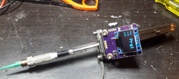
Through-hole chips are slowly falling by the wayside, and if you want to build something with new parts you will be using surface mount components. This means spreading paste and throwing it in the toaster oven. Of course, if you don’t want to take the time to get a stencil for your solder paste, you can always lay it down by hand. For that, [owhite] has created a tiny, handheld, robotic solder paste dispenser. It’s a robotic pen that dispenses just the right amount of solder paste on your pads.
The design of this solder paste dispenser is basically a syringe filled with paste and a stepper motor to push the plunger down. Devices like this already exist, and the i-extruder can be had for somewhere around two hundred bucks. Why buy when you can build, so [owhite] set out to create his own.
The key to a successful solder paste pen, it seems, is driving the plunger with a small NEMA 8 stepper motor, using a very fine pitch on the threads of the gears pushing the plunger down, and surprisingly finding a small-diameter syringe. [owhite] found the last bit in the form of a gas-tight syringe with a nylon gasket. The electronics consist of just a Teensy 3.2, DRV8825 stepper driver, footswitch, and an OLED for a UI.
With just a few parts, [owhite] managed to create a solder paste pen that’s better than the commercial i-extruder, and with a bit of practice can be used to place paste on some SMD pads.
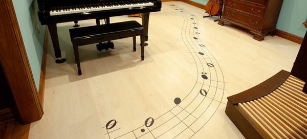
It’s been a few years since we first started hearing about “tools of the future changing the way we work” but this astounding whole-room floor inlay might be the best argument for them yet.
The Shaper Origin
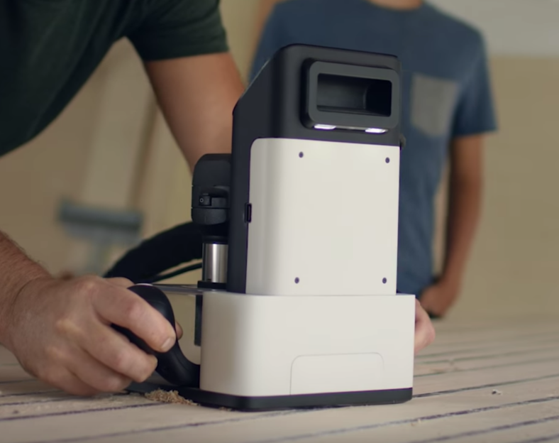
A couple of years ago we wrote a hands-on preview of a unique tool called the Shaper Origin. If a milling machine is classically defined as having a stationary tool head with moving stock, the Origin is the reverse. To use an Origin the user adheres specially marked tape to the stock material, then holds the origin down and moves it much like a hand router.
The Origin has a camera which tracks the fiducial patterns on the tape, allowing it to know its precise position, even across an entire room. The operator sees a picture on the screen of the tool that guides them with superimposed lines, while the tool head makes its own precision adjustments to perfectly cut the design in the X, Y, and Z.
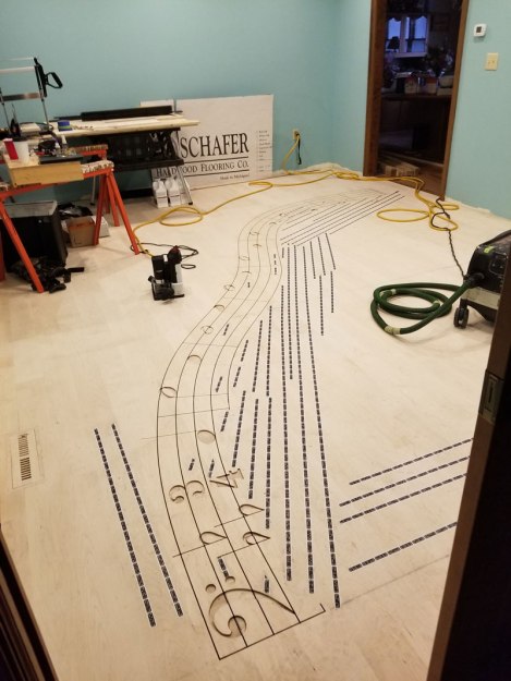
Floor in Progress
But what do you use a tool like this for? Cutting boards, small tables, and toy blocks are fine examples but don’t highlight any unique features of the tool. Many could just as easily be made using a ShopBot, X-Carve, Carvey, or any of their ilk. What you can’t do with any of those tools (or really anything besides manual labor, endless patience, and master skill) is inlay an entire floor in situ.
[Mark Scheller] (eight time winner of Wood Floor of the Year awards) used an Origin to cut a curvaceous 22 foot long rendition of the first 9 bars of Handel’s Passacaglia into the floor of a lucky homeowner’s music room. Without decades of practice, it’s difficult to imagine doing this any way besides with a Shaper Origin. You can’t put an entire room into a CNC router. The individual floorboards could be cut, but that would be tedious and increasingly difficult as the room gets larger. With the Origin it seems almost trivial. Do the design, place the marking tape, and cut. The same model is used to cut the inlays for a perfect fit. This is an incredible example of a unique use for this unusual tool!