The look, the feel, the sound — there are few things more satisfying in this world than a nice switch. If you’re putting together a device that you plan on using frequently, outfitting it with high-quality switches is one of those things that’s worth the extra cost and effort.
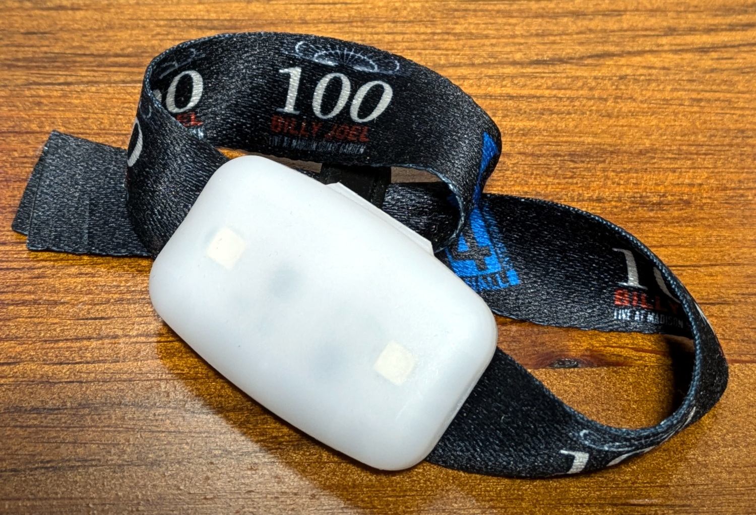
So we understand completely why [STR-Alorman] went to such great lengths to get the aftermarket seat heaters he purchased working with the gorgeous switches Toyota used in the 2006 4Runner. That might not sound like the kind of thing that would involve reverse engineering hardware, creating a custom PCB, or writing a bit of code to tie it all together. But of course, when working on even a halfway modern automobile, it seems nothing is ever easy.
 The process started with opening up the original Toyota switches and figuring out how they work. The six-pin units have a lot going on internally, with a toggle, a rheostat, and multiple lights packed into each one. Toyota has some pretty good documentation, but it still took some practical testing to distill it down into something a bit more manageable. The resulting KiCad symbol for the switch helps explain what’s happening inside, and [STR-Alorman] has provided a chart that attributes each detent on the knob with the measured resistance.
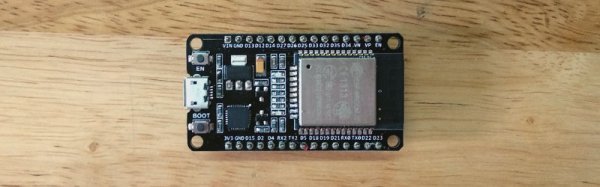
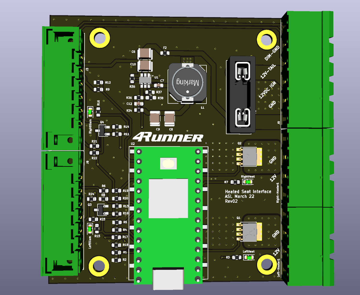
But understanding how the switches worked was only half the battle. The aftermarket seat heaters were only designed to work with simple toggles, so [STR-Alorman] had to develop a controller that could interface with the Toyota switches and convince the heaters to produce the desired result. The custom PCB hosts a Teensy 3.2 that reads the information from both the left and right seat switches, and uses that to control a pair of beefy MOSFETs. An interesting note here is the use of very slow pulse-width modulation (PWM) used to flip the state of the MOSFET due to the thermal inertia of the heater modules.
We love the effort [STR-Alorman] put into documenting this project, going as far as providing the Toyota part numbers for the switches and the appropriate center-console panel with the appropriate openings to accept them. It’s an excellent resource if you happen to own a 4Runner from this era, and a fascinating read for the rest of us.