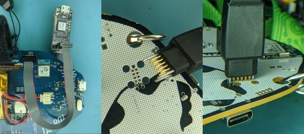
The Amazon Dash Button: A Retrospective

The Internet of Things will revolutionize everything! Manufacturing? Dog walking? Coffee bean refilling? Car driving? Food eating? Put a sensor in it! The marketing makes it pretty clear that there’s no part of our lives which isn’t enhanced with The Internet of Things. Why? Because with a simple sensor and a symphony of corporate hand waving about machine learning an iPhone-style revolution is just around the corner! Enter: Amazon Dash, circa 2014.

The first product in the Dash family was actually a barcode scanning wand which was freely given to Amazon Fresh customers and designed to hang in the kitchen or magnet to the fridge. When the Fresh customer ran out of milk they could scan the carton as it was being thrown away to add it to their cart for reorder. I suspect these devices were fairly expensive, and somewhat too complex to be as frequently used as Amazon wanted (thus the extremely limited launch). Amazon’s goal here was to allow potential customers to order with an absolute minimum of friction so they can buy as much as possible. Remember the “Buy now with 1-Click” button?
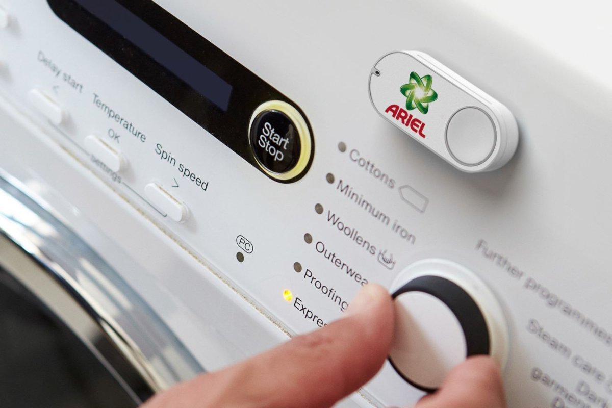
That original Dash Wand was eventually upgraded to include a push button activated Alexa (barcode scanner and fridge magnet intact) and is generally available. But Amazon had pinned its hopes on a new beau. Mid 2015 Amazon introduced the Dash Replenishment Service along with a product to be it’s exemplar – the Dash Button. The Dash Button was to be the 1-Click button of the physical world. The barcode-scanning Wands require the user to remember the Wand was nearby, find a barcode, scan it, then remember to go to their cart and order the product. Too many steps, too many places to get off Mr. Bezos’ Wild Ride of Commerce. The Dash Buttons were simple! Press the button, get the labeled product shipped to a preconfigured address. Each button was purchased (for $5, with a $5 coupon) with a particular brand affinity, then configured online to purchase a specific product when pressed. In the marketing materials, happy families put them on washing machines to buy Tide, or in a kitchen cabinet to buy paper towels. Pretty clever, it really is a Buy now with 1-Click button for the physical world.

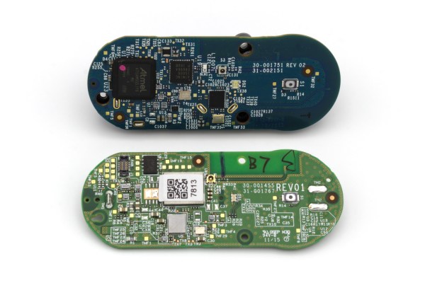
There were two versions of the Dash button. Both have the same user interface and work in fundamentally the same way. They have a single button (the software can recognize a few click patterns), a single RGB LED (‘natch), and a microphone (no, it didn’t listen to you, but we’ll come back to this). They also had a WiFi radio. Version two (silently released in 2016) added Bluetooth and completely changed the electrical innards, though to no user facing effect.

In February 2019, Amazon stopped selling the Dash Buttons. Continue reading “The Amazon Dash Button: A Retrospective”

Debug Superpowers Bring An STM32 Back From The Dead

When a processor has a fault it can leave what looks to be precious little in the way of cause and effect. Debug-by-print-statement works surprisingly well in simple cases, but where in a desktop environment you would drop into a debugger to solve trickier problems this can be an onerous task on an embedded system. [Ross Schlaikjer]’s excellent blog post walks through setting up one of our favorite Open Hardware debug probes and shows us that with the right tooling in place, unexpected faults aren’t quite so impenetrable. Continue reading “Debug Superpowers Bring An STM32 Back From The Dead”

STEP Up Your Jetson Nano Game With These Printable Accessories

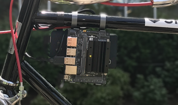
Found yourself with a shiny new NVIDIA Jetson Nano but tired of having it slide around your desk whenever cables get yanked? You need a stand! If only there was a convenient repository of options that anyone could print out to attach this hefty single-board computer to nearly anything. But wait, there is! [Madeline Gannon]’s accurately named jetson-nano-accessories repository supports a wider range of mounting options that you might expect, with modular interconnect-ability to boot!

A device like the Jetson Nano is a pretty incredible little System On Module (SOM), more so when you consider that it can be powered by a boring USB battery. Mounted to NVIDIA’s default carrier board the entire assembly is quite a bit bigger than something like a Raspberry Pi. With a huge amount of computing power and an obvious proclivity for real-time computer vision, the Nano is a device that wants to go out into the world! Enter these accessories.

At their core is an easily printable slot-and-tab modular interlock system which facilitates a wide range of attachments. Some bolt the carrier board to a backplate (like the gardening spike). Others incorporate clips to hold everything together and hang onto a battery and bicycle. And yes, there are boring mounts for desks, tripods, and more. Have we mentioned we love good documentation? Click into any of the mount types to find more detailed descriptions, assembly directions, and even dimensioned drawings. This is a seriously professional collection of useful kit.

Micro-Sized Flex For Commercial Quality Bodging

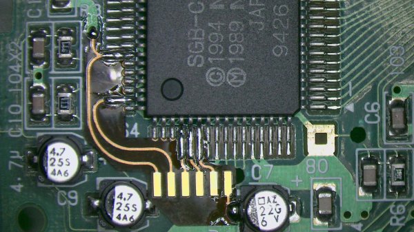
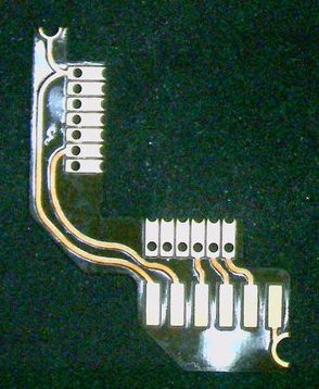
We love watching the creativity unleashed by the democratization of once-exotic technologies. The casualness by which one can order a cheap, small run of PCBs has unlocked a flood of fine pitch components and projects which look commercial quality even with a total build volume of one. Now the once mythical flex PCB has been falling from it’s stratospheric pricing and with OSHPark’s offering it feels like we’re at the inflection point. [qwertymodo] leveraged this by creating a beautifully twisted flex to add link port support to the Super Game Boy

In the mid-90’s Nintendo released the Super Game Boy, a cartridge for the SNES which allowed you to play Game Boy games on the big screen. Each cartridge was in fact an entire Game Boy with the appropriate hardware to present it in a way the host console could interface with, but missing some of the hardware a standalone Game Boy would include like a link port to connect it to another system. This mod fixes this limitation by bridging the correct pins out from the CPU to a breakout board which includes the link port connector. For general background on what’s going on here, check out [Brian]’s article from April describing a different mod [qwertymodo] executed to the same system.
What’s fascinating is how elegant the mod is. Using a a flex here to create a completely custom, strangely shaped, one-of-a-kind adapter for this random IC, in low volume is an awesome example of the use of advanced manufacturing techniques to take our hacks to the next level. It reminds us a little of the method [Scotty] used to add the headphone jack to his iPhone 7 back in 2017. At the time that seemed like a technology only available to hackers who could speak a little Mandarin and lived in Shenzhen.

Detailed information on this hack is a little spread out. There is slightly more info in these tweets, and if you have a Super Game Boy crying out for a link port the adapter flexes are sometimes available here. Look beyond the break to see what the mod originally looked like sans-flex.

Continue reading “Micro-Sized Flex For Commercial Quality Bodging”

A New KiCAD Tutorial Hits The Scene

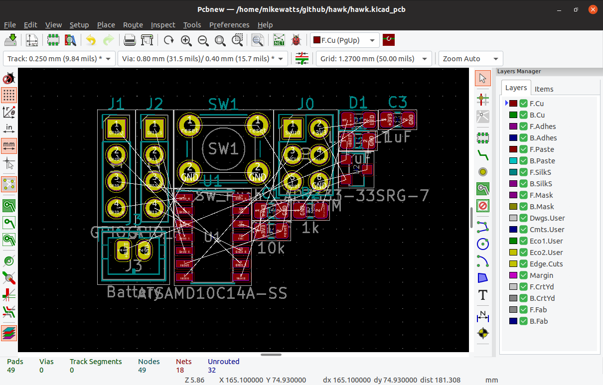
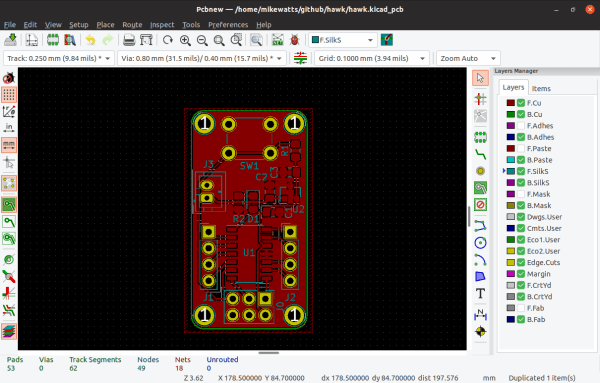
KiCAD has a rightfully earned image problem regarding beginners. The shiny new version 5 has improved things (and we’re very excited for v6!) but the tool is a bit obtuse even when coming from a electronics design background, so we’re always excited to see new learning material. [Mike Watts] is the latest to join the esteemed group of people willing to export their knowledge with his KiCAD tutorial series on GitHub that takes the aspiring user from schematic through fab and assembly.

The tutorial is focused around the process of creating a development board for the dimuitive Microchip née Atmel ATSAMD10 Cortex M0 ARM CPU. It opens by asking the reader to create a schematic and proceeds to teach by directing them to perform certain actions then explaining what’s going on and which shortcuts can accelerate things. This method continues through layout, manufacturing, and assembly.

Of note is that when defining the board outline [Mike] describes how to use OpenSCAD to parametrically define it; a neat micro-tutorial on using the two great tools to compliment each other. We also love that upon successful completion of the tutorial series the user will have developed a tiny but useful development board that can be assembled for about $3 in single quantities!

As with all open source work, if you have quibbles or want to contribute open a pull request and give [Mike] a hand!

High Precision Analog IO With Digital Pins

Reading the temperature of your environment is pretty easy right? A quick search suggests the utterly ubiquitous DHT11, which speaks a well documented protocol and has libraries for every conceivable microcontroller and platform. Plug that into your Arduino and boom, temperature (and humidity!) readings. But the simple solution doesn’t hit every need, sometimes things need to get more esoteric.

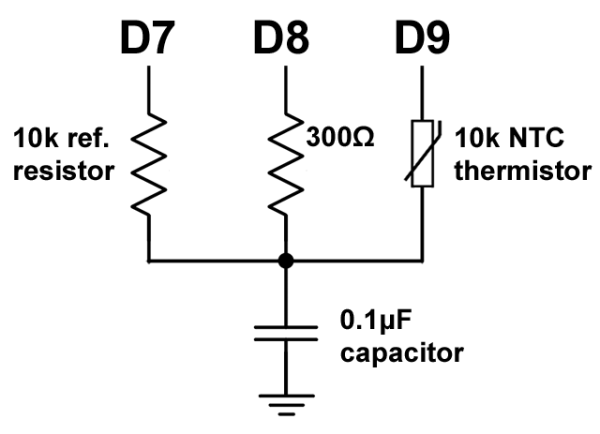
The technique summarized by an image from Microchip Appnote AN685

For years we’ve been watching [Edward]’s heroic efforts to build accessible underwater sensing hardware. When we last heard from him he was working on improving the accuracy of his Arduino’s measurements of the humble NTC thermistor. Now the goal is the same but he has an even more surprising plan, throw the ADC out entirely and sample an analog thermistor using digital IO. It’s actually a pretty simple trick based on an intuitive observation, that microcontrollers are better at measuring time than voltage. 

The basic circuit

The circuit has a minimum of four components: a reference resistor, the thermistor, and a small capacitor with discharge resistor. To sense you configure a timer to count, and an edge interrupt to capture the value in the timer when its input toggles. One sensing cycle consists of discharging the cap through the discharge resistor, enabling the timer and interrupt, then charging it through the value to measure. The value captured from the timer will be correlated to how long it took the cap to charge above the logic-high threshold when the interrupt triggers. By comparing the time to charge through the reference against the time to charge through the thermistor you can calculate their relative resistance. And by performing a few calibration cycles at different temperatures ([Edward] suggests at least 10 degrees apart) you can anchor the measurement system to real temperature.

For all the gory details, including tips for how to save every last joule of energy, check out [Edward]’s post and the Microchip appnote AN685 he references. Besides this series [Edward]’s Cave Pearl Project has already yielded an impressive number of Hackday posts. For more great hardware writeups check out a general hardware build for a single sensing node, or the “temperature sensor” [Edward] made with no external parts at all!

An Epic Tale Of Thermistors: Tricks For Much Better Temperature Sensing

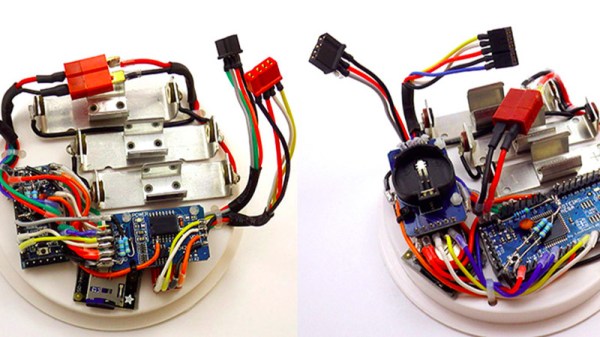
For years [Edward] has been building professional grade underwater sensing nodes at prices approachable for an interested individual without a government grant. An important component of these is temperature, and he has been on a quest to get the highest accuracy temperature readings from whatever parts hit that sweet optimum between cost and complexity. First there were traditional temperature sensor ICs, but after deploying numerous nodes [Edward] was running into the limit of their accuracy. Could he use clever code and circuitry to get better results? The short answer is yes, but the long answer is a many part series of posts starting in 2016 detailing [Edward]’s exploration to get there.

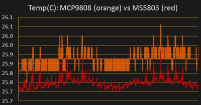
Orange is 12 bits, red is 24

The first step is a thermistor, a conceptually simple device: resistance varies with temperature (seriously, how much more simple can a sensor get?). You can measure them by tapping the center of a voltage divider the same way you’d measure any other resistance, but [Edward] had discarded this idea because the naive approach combined with his Arduino’s 10 bit ADC yielded resolution too poor to be worthwhile for his needs. But by using the right analog reference voltage and adjusting the voltage divider he could get a 20x improvement in resolution, down to 0.05°C in the relevant temperature range. This and more is the subject of the first post.

What comes next? Oversampling. Apparently fueled by a project featured on Hackaday back in 2015 [Edward] embarked on a journey to applying it to his thermistor problem. To quote [Edward] directly, to get “n extra bits of resolution, you need to read the ADC four to the power of n times”. Three bits gives about an order of magnitude better resolution. This effectively lets you resolve signals smaller than a single sample but only if there is some jitter in the signal you’re measuring. Reading the same analog line with no perturbation gives no benefit. The rest of the post deals with the process of artificially perturbing the signal, which turns out to be significantly complex, but the result is roughly 16 bit accuracy from a 10 bit ADC!

What’s the upside? High quality sensor readings from a few passives and a cheap Arduino. If that’s your jam check out this excellent series when designing your next sensing project!