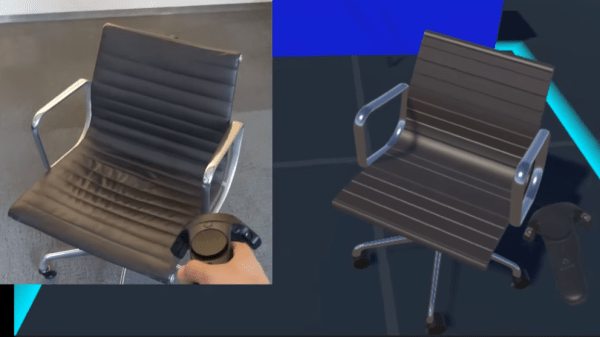
Hackaday Prize Entry: FabDoc Is Version Control For Project Images

FabDoc is an interesting concept that attempts to tackle a problem many of us didn’t realize we had. There are plenty of version control systems for software, but many projects also have a hardware element or assembly process. Those physical elements need to be documented, but that process does not easily fit the tools that make software development and collaboration easier. [Kevin Cheng] sums FabDoc up as “a system to capture time-lapse pictures as pre-commits.”

With FabDoc a camera automatically records the physical development process, allowing the developer to focus on work and review later. The images from the camera are treated as pre-commits. Upon review, the developer selects relevant key images (ignoring dead ends or false starts) and commits them. It’s a version control and commit system for the physical part of the development process. The goal is to remove the burden of stopping the work process in order to take pictures, automatically record the development process and attach it to a specific project, and allow easy management of which images to commit.

The current system uses a Raspberry Pi Zero with a camera mounted on safety glasses, and some support software. Some thought has certainly gone into making the system as easy to use and manage as possible; after setting up a repository, scanning a QR code takes care of telling the system what to do and where to put it. The goal is to make FabDoc fast and easy to use so that it can simply work unattended.

We saw a visual twist on version control some time ago with a visual diff for PCBs, which was a great idea to represent changes between PCB designs visually, diff-style. It’s always exciting to see someone take a shot at improving processes that are easy to take for granted.

Books You Should Read: IGNITION!

Isaac Asimov described the business of rocket fuel research as “playing footsie with liquids from Hell.” If that piques your interest even a little, even if you do nothing else today, read the first few pages of IGNITION! which is available online for free. I bet you won’t want to stop reading.

IGNITION! An Informal History of Liquid Rocket Propellants is about how modern liquid rocket fuel came to be. Written by John D. Clark and published in 1972, the title might at first glance make the book sound terribly dry — it’s not. Liquid rocket fuel made modern rocketry possible. But most of us have no involvement with it at all besides an awareness that it exists, and that makes it easy to take for granted.

Most of us lack any understanding of the fact that its development was the result of a whole lot of hard scientific work, and that work required brilliance (and bravery) and had many frustrating dead ends. It was also an amazingly dangerous business to be in. Isaac Asimov put it this way in the introduction:

“[A]nyone working with rocket fuels is outstandingly mad. I don’t mean garden-variety crazy or a merely raving lunatic. I mean a record-shattering exponent of far-out insanity.

There are, after all, some chemicals that explode shatteringly, some that flame ravenously, some that corrode hellishly, some that poison sneakily, and some that stink stenchily. As far as I know, though, only liquid rocket fuels have all these delightful properties combined into one delectable whole.”

At the time that the book was written and published, most of the work on liquid rocket fuels had been done in the 40’s, 50’s, and first half of the 60’s. There was plenty written about rocketry, but very little about the propellants themselves, and nothing at all written about why these specific substances and not something else were being used. John Clark — having run a laboratory doing propellant research for seventeen years — had a unique perspective of the whole business and took the time to write IGNITION! An Informal History of Liquid Rocket Propellants.

Liquid rocket propellant was in two parts: a fuel and an oxidizer. The combination is hypergolic; that is, the two spontaneously ignite and burn upon contact with each other. As an example of the kinds of details that mattered (i.e. all of them), the combustion process had to be rapid and complete. If the two liquids flow into the combustion chamber and ignite immediately, that’s good. If they form a small puddle and then ignite, that’s bad. There are myriad other considerations as well; the fuel must burn at a manageable temperature (so as not to destroy the motor), the energy density of the fuel must be high enough to be a practical fuel in the first place, and so on.

The actual process of discovering exactly what materials to use and how precisely to make them work in a rocket motor was the very essence of the phrase “the devil is in the details.” For every potential solution, there was a mountain of dead-end possibilities that tantalizingly, infuriatingly, almost worked.

The first reliable, workable propellant combination was Aniline and Red Fuming Nitric Acid (RFNA). “It had the one – but magnificent – virtue that it worked,” writes Clark. “Otherwise it was an abomination.” Aniline was difficult to procure, ferociously poisonous and rapidly absorbed through skin, and froze at an inconvenient -6.2 Celsius which limited it to warm weather only. RFNA was fantastically corrosive, and this alone went on to cause no end of problems. It couldn’t be left sitting in a rocket tank waiting to be used for too long, because after a while you wouldn’t have a tank left. It needed to be periodically vented while in storage. Pouring it gave off dense clouds of remarkably toxic gas. This propellant would go on to cause incredibly costly and dangerous problems, but it worked. Still, no one wanted to put up with any of it one moment longer than they absolutely had to. As a result, that combination was not much more than a first step in the whole process; there was plenty of work left to do.

By the mid-sixties, liquid rocket propellant was a solved problem and the propellant community had pretty much worked themselves out of a job. Happily, a result of that work was this book; it captures history and detail that otherwise would simply have disappeared.

Clark has a gift for writing, and the book is easy to read and full of amusing (and eye-widening) anecdotes. Clark doesn’t skimp on the scientific background, but always in an accessible way. It’s interesting, it’s relevant, it’s relatable, and there is plenty to learn about how hard scientific and engineering development actually gets done. Download the PDF onto your favorite device. You’ll find it well worth the handful of evenings it takes to read through it.

Rushing The Design And Construction Of LED Centerpieces

‘Dragon Flame’ RGB LED table centerpieces, by [Alex Lao]
Sometimes the most important thing is getting something done.

[Alex Lao] was recently in such a situation. His sister was getting married and he designed, built, and delivered twenty RGB LED table centerpieces in a rush. There were no prototypes made, and when the parts arrived all twenty were built all at once over a single weekend. These table centerpieces are illuminated by RGB LEDs and battery-powered, but have an option to be powered by a wall adapter.

[Alex] helpfully shared some tips on reducing the production risks and helping ensure results in such a limited time frame. His advice boils down to this: reduce the unknowns. For Alex this meant re-using code and components from a previous project — even if they were not optimal — so that known-good schematic and footprint libraries could be used for the design.

From one perspective, the PIC32 microcontroller inside each lamp is overkill for an LED centerpiece. From another perspective, it was in fact the perfect part to use because it was the fastest way for [Alex] to get the devices working with no surprises.

For an added perspective on needing to get production right the first time on a much larger scale, be sure to check out getting an installation made up of 25,000 PCBs right the first time.

3D Printing Flexible Surfaces Out Of Non-Flexible Material

Here’s some interesting work shared by [Ben Kromhout] and [Lukas Lambrichts] on making flexible 3D prints, but not by using flexible filament. After seeing a project where a sheet of plywood was rendered pliable by cutting a pattern out of it – essentially turning the material into a giant kerf bend – they got interested in whether one could 3D print such a thing directly.

Inspiration for the project was this laser-cut plywood.

The original project used plywood and a laser cutter and went through many iterations before settling on a rectangular spiral pattern. The results were striking, but the details regarding why the chosen pattern was best were unclear. [Ben] and [Lukas] were interested not just in whether a 3D printer could be used to get a similar result, but also wanted to find out what factors separated success from failure when doing so.

After converting the original project’s rectangular spiral pattern into a 3D model, a quick proof-of-concept showed that three things influenced the flexibility of the end result: the scale of the pattern, the size of the open spaces, and the thickness of the print itself. Early results indicated that the size of the open spaces between the solid elements of the pattern was one of the most important factors; the larger the spacing the better the flexibility. A smaller and denser pattern also helps flexibility, but when 3D printing there is a limit to how small features can be made. If the scale of the pattern is reduced too much, open spaces tend to bridge which is counter-productive.

Kerf bending with laser-cut materials gets some clever results, and it’s interesting to see evidence that the method could cross over to 3D printing, at least in concept.

Edge-lit Pendants Show Two Layers Are Better Than One

Engraved acrylic lights up nicely with LED lighting. Simply engrave clear acrylic with a laser engraver, then edge-light the acrylic and watch the engraving light up. This badge made by [Solarbotics] shows how they used this principle when creating some pendants for an event that performed particularly well in the dark.

The pendants they created have two engraved acrylic panels each, and that’s about it. Two LEDs and a CR2032 battery nestle into pre-cut holes, and the engraved sides are placed face-to-face, so the outer surfaces of the pendant are smooth. By using some color-cycling RGB LEDs on one panel and blue LEDs on the other panel, the effect is that of an edge-lit outer design with a central element that slowly changes color separately from the rest of the pendant.

The design stacks the LED leads and coin cells in such a way that a simple wrap of tape not only secures things physically, but also takes care of making a good electrical connection. No soldering or connectors of any kind required. [Solarbotics] found that CR2032 cells would last anywhere between a couple of days to a week, depending on the supplier.

This design is great for using a minimum of materials, but if that’s not a priority it’s possible to go much further with the concept. Multiple layers of edge-lit acrylic were used to make numeric 0-9 display modules as well as a full-color image.


This Method Of Gluing Onto Curves Sucks!

Sometimes the right tool for a job can be unusual, and this sucked only in the sense that vacuum sealing was involved. Recently [Martin Raynsford] found himself in a situation of needing to glue a wood veneer onto a curved surface, but faced a shortage of clamps. His clever solution was to vacuum-seal the whole thing and let the contour-hugging plastic bag take care of putting even pressure across the entire glued surface. After the glue had set enough to grip the materials securely, the bag was removed to let the whole thing dry completely. Gluing onto a curved surface has never been so clamp-free.

The curved piece in question was made from dozens of layers of laser-cut plywood, stacked and glued to make the curved lid of a custom-built chest. It might have been just the right shape, but it wasn’t much to look at. As you can see, giving it a wood veneer improved the appearance considerably. Wood veneers are attractive and versatile; we’ve seen for example that LEDs will shine through wood veneer quite easily.

DIY Illuminator For UV Fluorescence Photography

The image shown is the mineral Hackmanite, which fluoresces under ultraviolet lighting. However, not all UV is created equal, and that makes a difference if you’re into UV imaging. The image for this article is from [David Prutchi] and shows the striking results of using different wavelengths of UV. [David] goes into detail on how to make your own DIY Long, Medium, and Short-wave UV Illuminator complete with part numbers and wiring diagram. The device isn’t particularly complicated; the real work was determining the exact part numbers and models of lamp, filters, and ballasts required to get the correct results. [David] has done that work and shared it for anyone interested in serious UV fluorescence photography, along with a white paper on the process.

We’ve seen [David]’s work before. We featured his DIY short-wave UV imager in the past, and his DOLPi camera project was a 2015 Hackaday Prize finalist. It’s clear he really knows his stuff, and genuinely enjoys sharing his discoveries and work.