Personal Electric Vehicles (PEVs) all contain the same basic set of parts: a motor, a battery, a motor controller, some sensors, and a display to parse the information. This simplicity allowed [casainho] to develop a custom controller setup for their own PEVs.
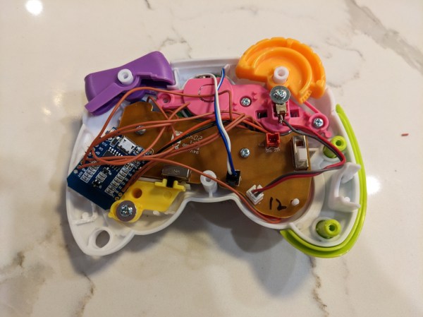
Built around the venerable VESC motor controller, [casainho]’s addition is the EBike/EScooter board that interfaces the existing motor of a device to the controller. Their ESP32-powered CircuitPython solution takes the sensor output of a given bike or scooter (throttle, cadence, or torque) and translates it into the inputs the controller uses to set the motor power.
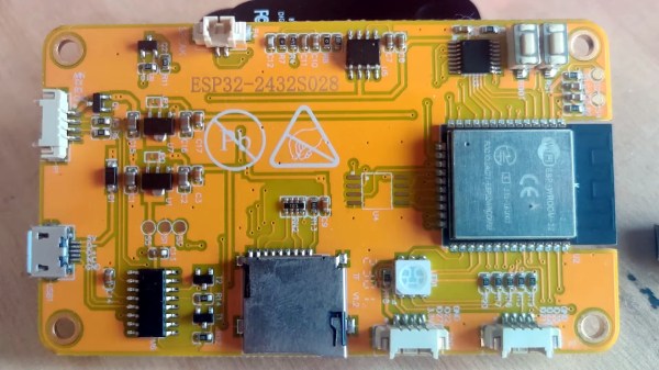
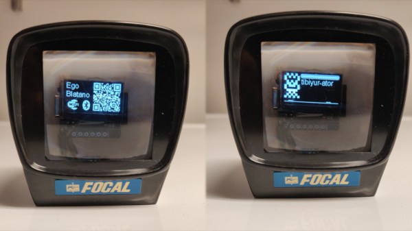
They’ve also designed an ESP32-based display to interface the rest of the system to the user while riding. Since it also runs CircuitPython, it’s easy to reconfigure the functions of the three button device to display whatever you’d like as well as change various drive modes of your system. I know I’d love to see my own ebikes have a different mode for riding on road versus on shared paths since not getting run over by cars and not harassing pedestrians aren’t going to have the same power profile.
If you want to find more ways to join the PEV revolution, check out this wild omni-wheeled bike or this solar car built from two separate e-bikes. If that doesn’t suit your fancy, how about an off-label use for an e-bike battery to power your laptop off grid?