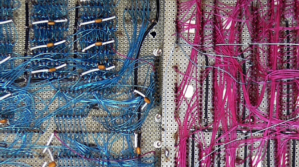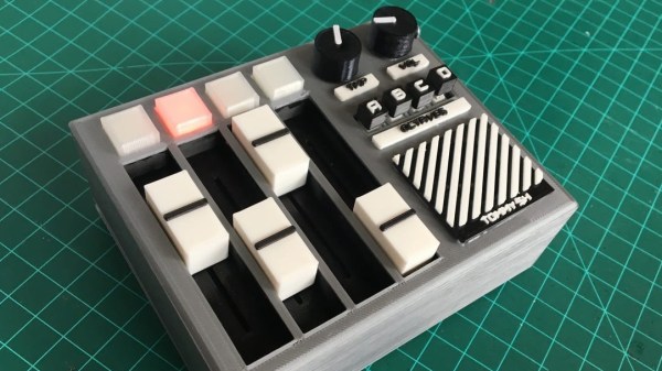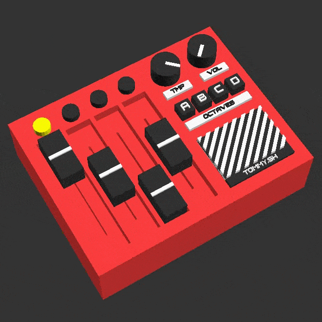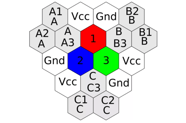
A breadboard is a great prototyping tool for verifying the sanity of a circuit design before taking the painstaking effort of soldering it all together permanently. After all, a mistake in this stage can cost a lot of time and possibly material, so it’s important to get it right. [daverowntree] wasn’t fully satisfied with the standard breadboard layout though, with fixed rows and columns. While this might work for most applications, he tried out a new type of prototyping board based on hexagons instead.
The design philosophy here revolves around tessellations, a tiling method for connecting the various components on this unique breadboard rather than using simple rows. The hexagons are tessellated across the board, allowing for some unique combinations that might make it slightly more complicated, but can have some benefits for other types of circuits such as anything involving the use of a three-wire device like a transistor.
The post is definitely worth a read, as [daverowntree] goes through several examples of this method of prototyping where the advantages are shown, like a voltage follower circuit and some other circuits involving transistor biasing. If you’re OK with the general design of breadboards, though, and just wished you didn’t have to do anything after the prototyping stage, we’ve got some help for you there as well.
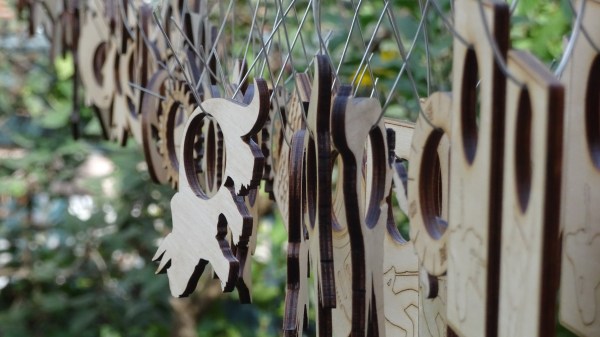
 It all began when the kids were taken to a local fab lab at the École Polytechnique and made some laser-cut napkin holders from plywood for personal use. Later, they decided to design, manufacture, and sell them at the Ottawa Maker Faire. Money for the plywood came from piggy banks, 23 different designs made the cut, and a total of 103 rings were made. A display board and signs made from reclaimed materials rounded out the whole set.
 That’s where [Andy Forest] comes in with the