Kitchen Timer

A Kitchen Timer Fit For MacGyver

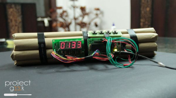
Here’s a project that you don’t want to bring into an airport, ship through the mail, or probably even remove from your home. [ProjectGeek] has built himself a simple kitchen timer masquerading as a bomb. The build is actually pretty simple, but the end result is something that would look at home in a Hollywood action flick.

The timer circuit is built from four simple components. An 8051 microcontroller board is used as the primary controller and timer. The code is available on GitHub. This board is attached to a another board containing four momentary push buttons. These are used to program the timer and to stop the buzzing. Another board containing four 7-segment displays is used to show the remaining time on the timer. A simple piezo buzzer is used to actually alert you when the timer has run out. All of these components are connected with colorful jumper wires.

The physical part of this build is made from easily available components. Old newspapers are rolled up to form the “explosive” sticks. These are then covered in plain brown paper ordinarily used to cover text books. The rolls are bundled together and fixed with electrical tape. The electronics can then be attached to the base with some hot glue or double-sided tape.

Volvo Phone Holder

DIY IPhone Mount For A Volvo

[Seandavid010] recently purchased a 2004 Volvo. He really liked the car except for the fact that it was missing some more modern features. He didn’t come stock with any navigation system or Bluetooth capabilities. After adding Bluetooth functionality to the stock stereo himself, he realized he would need a secure location to place his iPhone. This would allow him to control the stereo or use the navigation functions with ease. He ended up building a custom iPhone mount in just a single afternoon.

The key to this project is that the Volvo has an empty pocket on the left side of the stereo. It’s an oddly shaped vertical pocket that doesn’t seem to have any real use. [Seandavid010] decided this would be the perfect place to mount his phone. The only problem was that he didn’t want to make any permanent changes to his car. This meant no drilling into the dash and no gluing.

[Seandavid010] started by lining the pocket with blue masking tape. He then added an additional lining of plastic wrap. All of this was to protect the dashboard from what was to come next. He filled about half of the pocket with epoxy putty. We’ve seen this stuff used before in a similar project. He left a small opening in the middle with a thick washer mounted perpendicular to the ground. The washer would provide a place for an off-the-shelf iPhone holder to mount onto. [Seandavid010] also placed a flat, wooden paint stirrer underneath the putty. This created a pocket that would allow him to route cables and adapters underneath this new mount.

After letting the epoxy putty cure for an hour, he removed the block from the pocket. The stick was then removed, and any gaps were filled in with putty. The whole block was trimmed and smooth down for a more streamlined look. Finally, it was painted over with some flat black spray paint to match the color of the dashboard. An aftermarket iPhone holder allows [Seandavid010] to mount his cell phone to this new bracket. The cell phone holder allows him to rotate the phone into portrait or landscape mode, and even is adjustable to accommodate different sized phones.

Double Pendulum

Powered Double Pendulum Is A Chaotic Display

If you’ve never seen a double pendulum before, it’s basically just a pendulum with another pendulum attached to the end. You might not think that’s anything special, but these devices can exhibit extremely chaotic behavior if enough energy is put into the system. The result is often a display that draws attention. [David] wanted to build his own double pendulum display, but he wanted to make it drive itself. The result is a powered double pendulum.

There aren’t many build details here, but the device is simple enough that we can deduce how it works from the demonstration video. It’s broken into two main pieces; the frame and the pendulum. The frame appears to be made mostly from wood. The front plate is made of three layers sandwiched together. A slot is cut out of the middle to allow a rail to slide up and down linearly. The rail is designed in such a way that it fits between the outer layers of the front plate like a track.

The pendulum is attached to the linear rail. The rail moves up and down and puts energy into the pendulum. This causes the pendulum to actually move and generate the chaotic behavior. The rail slides up and down thanks to an electric motor mounted to the base. The mechanics work similar to a piston on a crankshaft. The motor looks as though it is mounted to a wooden bracket that was cut with precision on a laser cutter. The final product works well, though it is a bit noisy. We also wonder if the system would be even more fun to watch if the rotation of the motor had an element of randomness added to it. Or he could always attach a paint sprayer to the end. Continue reading “Powered Double Pendulum Is A Chaotic Display”

Synth Guitar

Arduino Synth Guitar Really Rocks

[Gr4yhound] has been rocking out on his recently completed synth guitar. The guitar was built mostly from scratch using an Arduino, some harvested drum pads, and some ribbon potentiometers. The video below shows that not only does it sound good, but [Gr4yhound] obviously knows how to play it.

The physical portion of the build consists of two main components. The body of the guitar is made from a chunk of pine that was routed out by [Gr4yhound’s] own home-made CNC. Three circles were routed out to make room for the harvested Yamaha drum pads, some wiring, and a joystick shield. The other main component is the guitar neck. This was actually a Squire Affinity Strat neck with the frets removed.

For the electronics, [Gr4yhound] has released a series of schematics on Imgur. Three SoftPot membrane potentiometers were added to the neck to simulate strings. This setup allows [Gr4yhound] to adjust the finger position after the note has already been started. This results in a sliding sound that you can’t easily emulate on a keyboard. The three drum pads act as touch sensors for each of the three strings. [Gr4yhound] is able to play each string simultaneously, forming harmonies.

The joystick shield allows [Gr4yhound] to add additional effects to the overall sound. In one of his demo videos you can see him using the joystick to add an effect. An Arduino Micro acts as the primary controller and transmits the musical notes as MIDI commands. [Gr4yhound] is using a commercial MIDI to USB converter in order to play the music on a computer. The converter also allows him to power the Arduino via USB, eliminating the need for batteries.

Continue reading “Arduino Synth Guitar Really Rocks”

Hacking Oklahoma State University’s Student ID Cards

[Sam] took an information security class at Oklahoma State University back in 2013. For his final project, he and a team of other students had to find a security vulnerability and then devise a theoretical plan to exploit it. [Sam’s] team decided to focus on the school’s ID cards. OSU’s ID cards are very similar to credit cards. They are the same size and shape, they have data encoded on a magnetic strip, and they have a 16 digit identification number. These cards were used for several different purposes. Examples include photo ID, physical access to some areas on campus, charges to an online account, and more.

[Sam] and his team analyzed over 100 different cards in order to get a good sample. They found that all cards started with same eight digits. This is similar to the issuer identification number found in the first six digits of a credit card number. Th analysis also showed that there were only three combinations used for the next two digits. Those were either 05, 06, or 11. With that in mind, the total possible number of combinations for card numbers was mathematically calculated to be three million.

OSU also had a URL printed on the back of each card. This website had a simple form with a single field. The user can enter in a 16 digit card number and the system would tell the user if that card was valid. The page would also tell you if the card holder was an employee, a student, or if there were any other special flags on the card. We’re not sure why every student would need access to this website, but the fact is that the URL was printed right on the back of the card. The website also had no limit to how many times a query could be made. The only hint that the university was aware of possible security implications was the disclaimer on the site. The disclaimer mentioned that usage of the tool was “logged and tracked”.

The next step was to purchase a magnetic card reader and writer. The team decoded all of the cards and analyzed the data. They found that each card held an expiration date, but the expiration date was identical for every single card.  The team used the reader/writer to copy the data from [Sam’s] card and modify the name. They then wrote the data back onto a new, blank magnetic card. This card had no printing or markings on it. [Sam] took the card and was able to use it to purchase items from a store on campus. He noticed that the register reached back to a server somewhere to verify his real name. It didn’t do any checks against the name written onto the magstripe. Even still, the cashier still accepted a card with no official markings.

The final step was to write a node.js script to scrape the number verification website. With just 15 lines of code, the script will run through all possible combinations of numbers in a random sequence and log the result. The website can handle between three and five requests per second, which means that brute forcing all possible combinations can be completed in roughly two days. These harvested numbers can then be written onto blank cards and potentially used to purchase goods on another student’s account.

[Sam’s] team offers several recommendations to improve the security of this system. One idea is to include a second form of authorization, such as a PIN. The PIN wouldn’t be stored on the card, and therefore can’t be copied in this manner. The primary recommendation was to take down the verification website. So far OSU has responded by taking the website offline, but no other changes have been made.

Colorful Clock

A Colorful Clock For Toddlers

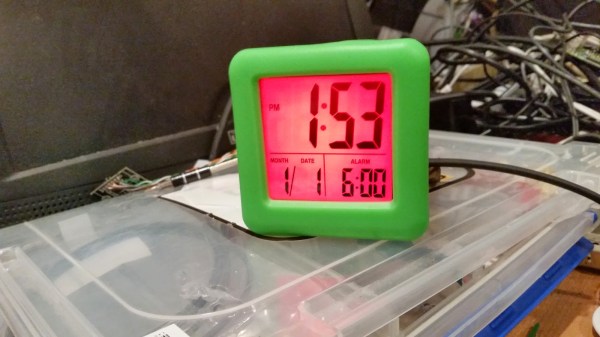
[Don] and his wife were looking for a way to teach their two-year old daughter how to tell time. She understood the difference between day and night, but she wasn’t old enough to really comprehend telling the actual time. [Don’s] solution was to simplify the problem by breaking time down into colored chunks representing different tasks or activities. For example, if the clock is yellow that might indicate that it’s time to play. If it’s purple, then it’s time to clean up your room.

[Don] started with a small, battery operated $10 clock from a local retailer. The simple clock had a digital readout with some spare room inside the case for extra components. It was also heavy enough to stay put on the counter or on a shelf. Don opened up the clock and got to work with his Dremel to free up some extra space. He then added a ShiftBrite module as a back light. The ShiftBrite is a high-brightness LED module that is controllable via Serial. This allows [Don] to set the back light to any color he wants.

[Don] already had a Raspberry Pi running his DIY baby monitor, so he opted to just hijack the same device to control the ShiftBrite. [Don] started out using a Hive13 GitHub repo to control the LED, but he found that it wasn’t suitable for this project. He ended up forking the project and altering it. His alterations allow him to set specific colors and then exit the program by typing a single command into the command line.

The color of the ShiftBrite is changed according to a schedule defined in the system’s crontab. [Don] installed Minicron, which provides a nice web interface to make it more pleasant to alter the cron job’s on the system. Now [Don] can easily adjust his daughter’s schedule via web page as needed.


Whiteboard Clock

Whiteboard Clock Draws The Time

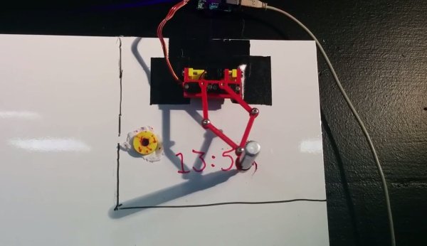
[Maurice] recently built a clock that draws the time (Google Doc) on a white board. We’ve seen plenty of clock hacks in the past, and even a very similar one. It’s always fun to see the different creative solutions people can come up with to solve the same problem.

This device runs on a PIC16F1454 microcontroller. The code for the project is available on GitHub. The micro is also connected to a 433MHz receiver. This allows a PC to keep track of the time, instead of having to include a real-time clock in the circuit. The USB connector is only used for power. All of the mounting pieces were designed in OpenSCAD and printed on a 3D printer. Two servos control the drawing arms. A third servo can raise and lower the marker to the whiteboard. This also has the added benefit of being able to place the marker tip inside of an eraser head. That way the same two servos can also erase the writing.

The communication protocol for this systems is interesting. The transmitter shows up on [Maurice’s] PC as a modem. All he needs to do to update the time is “echo 12:00 > /dev/whiteboard”. In this case, the command is run by a cron job every 5 minutes. This makes it easy to tweak the rate at which the time updates on the whiteboard. All communication is done one-way. The drawing circuit will verify the checksum each time it receives a message. If the check fails, the circuit simply waits for another message. The computer transmits the message multiple times, just in case there is a problem during transmission.