A Self-Expanding PWM Driver

For smaller microcontrollers, having enough outputs for the job is sometimes a challenge. A common solution is to do some sort of multiplexing with the available outputs or perhaps something more advanced such as Charlieplexing, but another good option is to use a specialized driver board. What’s even better is if you can daisy chain driver boards to get even more outputs.

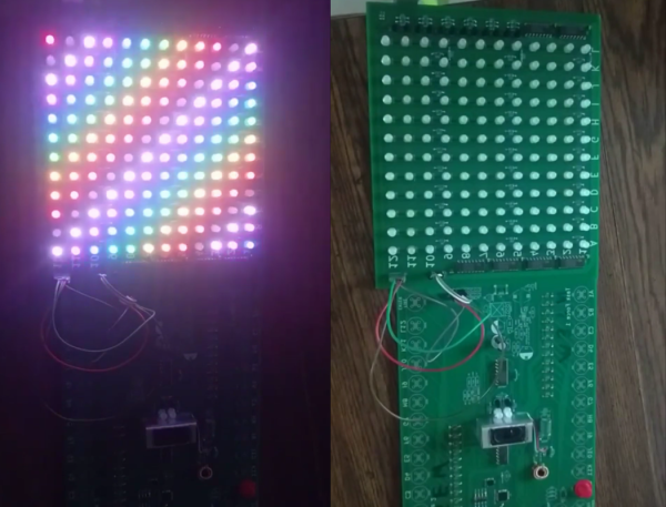
[Eric] has been working on a 16 channel LED project but first wanted to build a driver board with 8 channels. Before building a full 16 channel version he realized that he could take the same 8 channel board, make a mirror image of it, and attach it underneath the first board with headers in order to double the number of channels available. Without having to build a separate 16-channel board, this shortcut saved [Eric] some time and a great deal of effort.

This is a great example of working smarter, not harder. Each of the 8 or 16 channels has full PWM support as well to support PWM dimming, and a similar board could be built for motor control as well. It’s a good illustration of how good design can end up working for you as well. And if you need even more outputs, Charlieplexing is one way to get them.

Continue reading “A Self-Expanding PWM Driver”

Two Vintage Calculators In One

The FPGA revolution that occurred within the past few decades was a boon to many people interested in “antique” electronics. The devices “wire together” logic elements as needed rather than emulating chips completely in a software layer, which makes them uniquely suited for replicating chips that are rare, no longer in production, damaged, or otherwise lost. They also make it easy to experiment with hardware, like this project which combines two antique calculators into one single unit.

The two calculators used in this combination device are the TI Datamath and the Sinclair Scientific, both released in the early 1970s, the former of which has been extensively documented and reverse engineered on at least one occasion. The reproduction from [zpekic] has a toggle that allows the user to switch between the two “modes”. This showcases the power of microprogramming and microcode, and of the FPGA platform itself. Although both modes are functional, there are still a few bugs resulting from how different the two pieces of hardware were, which is really more of an interesting facet of this project than anything.

The build is a great showcase of FPGA technology, not to mention a great read-through for understanding these two calculators and their fundamental differences in data entry and manipulation, clock cycles, memory, and everything in between. It’s worth checking out, even if you don’t plan on using a decades-old calculator in your day-to-day life.

Weather Station Gets Much-Needed Upgrades

Weather stations are a popular project, partly because it’s helpful (and interesting) to know about the weather at your exact location rather than a forecast that might be vaguely in your zip code. They’re also popular because they’re a good way to get experience with microcontrollers, sensors, I/O, and communications protocols. Your own build may also be easily upgradeable as the years go by, and [Tysonpower] shows us some of the upgrades he’s made to the popular Sparkfun weather station from a few years ago.

The Sparkfun station is a good basis for a build though, it just needs some updates. The first was that the sensor package isn’t readily available though, but some hunting on Aliexpress netted a similar set of sensors from China. A Wemos D1 Mini was used as a replacement controller, and with it all buttoned up and programmed it turns out to be slightly cheaper (and more up-to-date) than the original Sparkfun station.

All of the parts and code for this new station are available on [Tysonpower]’s Github page, and if you want to take a look at a similar station that we’ve featured here before, there’s one from three years ago that’s also solar-powered.

Continue reading “Weather Station Gets Much-Needed Upgrades”

Numpy Comes To Micro Python

[Zoltán] sends in his very interesting implementation of a NumPy-like library for micropython called ulab.

He had a project in MicroPython that needed a very fast FFT on a micro controller, and was looking at all of the options when it occurred to him that a more structured approach like the one we all know and love in CPython would be possible on a micro controller too. He thus ended up with a python library that could do the FFT 50 times faster than the the pure Python implementation while providing all the readability and ease of use benefits that NumPy and Python together provide.

As cool as this is, what’s even cooler is that [Zoltan] wrote excellent documentation on the use of the library. Not only can this documentation be used for his library, but it provides many excellent examples of how to use MicroPython itself.

We really recommend that fans of Python and NumPy give this one a look over!

Creating A Bode Analyzer From A Microcontroller

Electrical engineers will recognize the Bode plot as a plot of the frequency response of a system. It displays the frequency on the x-axis and the phase (in degrees) or magnitude (in dB) on the y-axis, making it helpful for understanding a circuit or transfer function in frequency domain analysis.

[Debraj] was able to use a STM32F407 Discovery board to build a Bode analyzer for electronic circuits. The input to the analyzer is a series of sine wave signals with linearly increasing frequency, or chirps, preferably twenty frequencies/decade to keep the frequency range reasonable.

The signals from a DAC are applied to a target filter and the outputs (frequencies obtained) are read back through an ADC. Some calculations on the result reveal how much of the signal is attenuated and its phase, resulting in a Bode plot. The filtering is done through digital signal processing from a microcontroller.

While the signals initially ran through a physical RC-filter, testing the Bode plotter with different circuits made running the signals through a digital filter easier, since it eliminates the need to solder resistors and capacitors onto protoboards. Plotting is done using Python’s matplotlib, with the magnitude and phase of the output determined analytically.

It’s a cool project that highlights some of the capabilities of microcontrollers as a substitute for a pricier vector network analyzer.

Continue reading “Creating A Bode Analyzer From A Microcontroller”

Beam Me Up To The PCB Space Ship

This project would fit in perfectly with #BadgeLife if someone could figure out a way to hang it from their neck. Inspired by Star Trek’s Starship Enterprise, [bobricius] decided to design and assemble a miniature space ship PCB model, complete with 40 blinking LEDs controlled by an ATtiny85.

While the design uses 0603, 0802, 3014, 4014, and 0805 LEDs, some substitutions can be made since the smallest LEDs can be difficult to solder. The light effects include a green laser, plasma coils, a deflector with scrolling blue LEDs, and the main plate and bridge for the space ship.

The LEDs are controlled by charlieplexing, a technique for driving LED arrays with relatively few I/O pins, different from traditional multiplexing. Charlieplexing allows n pins to drive n2−n LEDs, while traditional multiplexing allows n pins to drive (n/2)2 LEDs. (Here is the best explanation of Charlieplexing we’ve ever seen.)

Especially with the compiled firmware running on the MCU, the PCB model makes for an impressive display.

The only catch? Your Starship Enterprise can’t actually fly.

Continue reading “Beam Me Up To The PCB Space Ship”

The Cutest Oscilloscope Ever Made

If you thought your handheld digital oscilloscope was the most transportable of your signal analyzing tools, then you’re in for a surprise. This oscilloscope made by [Mark Omo] measures only one square inch, with the majority of the space taken up by the OLED screen.

It folds out into an easier instrument to hold, and admittedly does require external inputs, so it’s not exactly a standalone tool. The oscilloscope runs on a PIC32MZ EF processor, achieving 20Msps and 1MHz of bandwidth. The former interleaves the processor’s internal ADCs in order to achieve its speed.

For the analog front-end the signals first enter a 1M ohm terminator that divide the signals by 10x in order to measure them outside the rails. They then get passed through a pair of diodes connected to the rails, clamping the voltage to prevent damage. The divider centers the incoming AC signal around 1.65V, halfway between AGND and +3.3V. As a further safety feature, a larger 909k Ohm resistor sits between the signals and the diodes in order to prevent a large current from passing through the diode in the event of a large voltage entering the system.

The next component is a variable gain stage, providing either 10x, 5x, or 1x gain corresponding to 1x, 0.5x, and 0.1x system gains. For the subsystem, a TLV3541 op-amp and ADG633 tripe SPDT analog switch are used to provide a power bandwidth around the system response due to driving concerns. Notably, the resistance of the switch is non-negligible, potentially varying with voltage. Luckily, the screen used in the oscilloscope needs 12V, so supplying 12V to the mux results in a lower voltage and thus a flatter response.

The ADC module, PIC32MZ1024EFH064, is a 12-bit successive approximation ADC. One advantage of his particular ADC is that extra bits of resolution only take constant time, so speed and accuracy can be traded off. The conversion starts with a sample and hold sequence, using stored voltage on the capacitor to calculate the voltage.

Several ADCs are used in parallel to sample at the same time, resulting in the interleaving improving the sample rate. Since there are 120 Megabits per second of data coming from the ADC module, the Direct Memory Access (DMA) peripheral on the PIC32MZ allows for the writing of the data directly onto the memory of the microcontroller without involving the processor.

The firmware is currently available on GitHub and the schematics are published on the project page.

Continue reading “The Cutest Oscilloscope Ever Made”