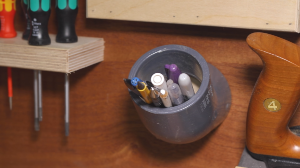
Pencils and pens are apt to go wandering in a busy workshop if they don’t have a handy storage spot. For most of us a soup can or an old coffee mug does the trick, but for a prettier and more useful holder [Stuff I Made] has a short video demonstrating a storage unit made from an elbow fitting and a scrap piece of plywood. He cuts a plywood disk that is friction-fit into one end of the elbow, then it gets screwed into a wall making an attractively flush-mounted holder in a convenient spot.
With the right joint the bottom of the holder remains accessible, as a 90 degree bend would be no good. With a shallower joint angle, a regular screwdriver can still reach the mounting screw and it’s possible to access the bottom of the holder just in case it needs cleaning or something small falls inside. You can see the process and results in the video embedded below. Not bad for one screw, a spare joint, and a scrap piece of plywood.
Continue reading “Give Workshop Pencils A Flush-Mounted Home”

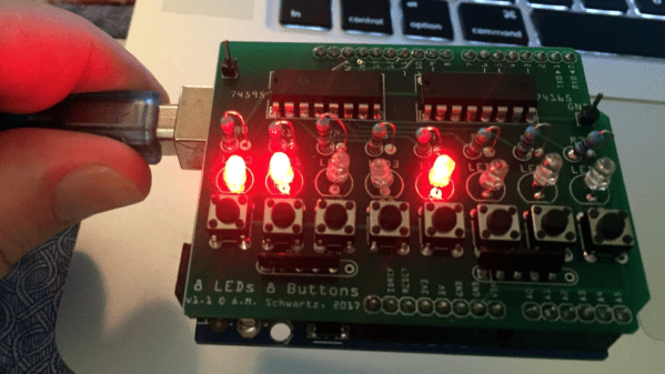
 [Allan] starts with a basic breadboard design, draws a schematic, prototypes the circuit, then designs the PCB and orders it online, followed by assembly and testing. [Allan] had previously taught himself to use
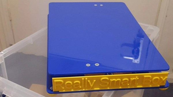
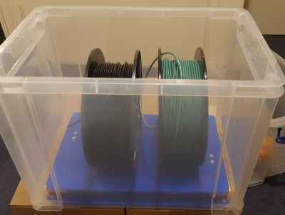 It does this by measuring the weight of the stuff piled on top of it, while also monitoring temperature and humidity. The platform communicates this information wirelessly to a back end, allowing decisions to be made about stock levels, usage, and monitoring of storage conditions. It’s clearly best applied to consumables or other stock that comes and goes. The Really Smart Box platform is battery-powered, but spends most of its time asleep to maximize battery life. The prototype uses the SigFox IoT framework for the wireless data, which we have seen before in a