Wildlife Camera

Remote Controlled Wildlife Camera With Raspberry Pi

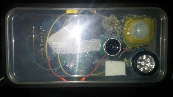
If you are interested in local wildlife, you may want to consider this wildlife camera project (Google cache). [Arnis] has been using his to film foxes and mice. The core components of this build are a Raspberry Pi and an infrared camera module specifically made for the Pi. The system runs on a 20,000 mAh battery, which [Arnis] claims results in around 18 hours of battery life.

[Arnis] appears to be using a passive infrared (PIR) sensor to detect motion. These sensors work by detecting sudden changes in the amount of ambient infrared radiation. Mammals are good sources of infrared radiation, so the sensor would work well to detect animals in the vicinity. The Pi is also hooked up to a secondary circuit consisting of a relay, a battery, and an infrared light. When it’s dark outside, [Arnis] can enable “night mode” which will turn on the infrared light. This provides some level of night vision for recording the furry critters in low light conditions.

[Arnis] is also using a Bluetooth dongle with the Pi in order to communicate with an Android phone. Using a custom Android app, he is able to connect back to the Pi and start the camera recording script. He can also use the app to sync the time on the Pi or download an updated image from the camera to ensure it is pointed in the right direction. Be sure to check out the demo video below.

If you like these wildlife cameras, you might want to check out some older projects that serve a similar purpose. Continue reading “Remote Controlled Wildlife Camera With Raspberry Pi”

TFT Display

Controlling A Color TFT Display With PIC32

Sometimes it feels like everyone out there is using Arduino. It’s easy to find tutorials and libraries to get things working with Arduino, but if you want to use another platform you might have more trouble. [Tahmid] ran into this problem when he decided to try using a PIC32 to control a 2.2″ color TFT display from Adafruit.

Adafruit is really good about providing tutorials and Arduino libraries for their products. It makes it really easy to get up and running… if you are using Arduino. All of their libraries are open source, which means that the community can take them and modify them as needed. [Tahmid] decided to do exactly this and fork the Adafruit libraries over to the PIC32 platform in C. It’s a great learning experience. You get to see how (good or bad) other people code, and it immerses you in the differences between two different chip families.

He’s released the libraries online for others to use. He says that he’s heavily commented the code to try to make as self-explanatory as possible. The display interfaces with the PIC32 using SPI. The demo video below shows the screen up and running and demonstrates the crisp color graphics. Continue reading “Controlling A Color TFT Display With PIC32”

Horn Antenna

Building A Horn Antenna For Radar

So you’ve built yourself an awesome radar system but it’s not performing as well as you had hoped. You assume this may have something to do with the tin cans you are using for antennas. The obvious next step is to design and build a horn antenna spec’d to work for your radar system. [Henrik] did exactly this as a way to improve upon his frequency modulated continuous wave radar system.

To start out, [Henrik] designed the antenna using CST software, an electromagnetic simulation program intended for this type of work. His final design consists of a horn shape with a 100mm x 85mm aperture and a length of 90mm. The software simulation showed an expected gain of 14.4dB and a beam width of 35 degrees. His old cantennas only had about 6dB with a width of around 100 degrees.

The two-dimensional components of the antenna were all cut from sheet metal. These pieces were then welded together. [Henrik] admits that his precision may be off by as much as 2mm in some cases, which will affect the performance of the antenna. A sheet of metal was also placed between the two horns in order to reduce coupling between the antennas.

[Henrik] tested his new antenna in a local football field. He found that his real life antenna did not perform quite as well as the simulation. He was able to achieve about 10dB gain with a field width of 44 degrees. It’s still a vast improvement over the cantenna design.

If you haven’t given Radar a whirl yet, check out [Greg Charvat’s] words of encouragement and then dive right in!

Excel Password

Breaking Dridex Malware With Excel Macro Password Exploit

[Ronnie] recently posted a new chapter in his adventures in malware deconstruction. This time the culprit was an infected Excel spreadsheet file. The .xls file was attached to a phishing email claiming to be related to a tax rebate. With tax season in full swing, this type of phishing message would be likely to be opened by an inexperienced user.

[Ronnie] saved the file to a virtual machine to prevent his real workstation from getting infected. He then opened it up in Excel and noticed that it immediately attempted to run macros. A macro is essentially visual basic scripting that runs inside of the spreadsheet file. You can use it for simple automation, cell formatting, or do even more complicated tasks like reach out to external websites and pull information. This malware focused on the latter.

[Ronnie] used the alt + F11 shortcut to view the macros. Unfortunately the attackers had password protected them. [Ronnie] wouldn’t be able to view the macro code without knowing the password. Luckily, he learned of a surprisingly simple trick to completely bypass the macro password. He opened up the .xls file in Notepad++ and located three keys; CMG, DPB, and G. [Ronnie] then created and saved a new blank .xls document and password protected the macros with his own password. He opened up this new file in Notepad++ as well, and located those same three keys. He copied the keys from the new file into the old one, and saved the old file. This effectively changed the password of the malware file to the new one he had set for his new file. This is a nifty trick that apparently only works on the older .xls formats, not the newer .xlsx format.

After loading the macros, [Ronnie] quickly noticed that most of the code was obfuscated to make it difficult to analyze. There were, however, three named modules that reference possible sandbox evasion techniques. The malware first invokes these functions to detect the presence of a virtual machine or other type of sandbox. If it detects nothing, then the rest of the malware program is decoded and executed. [Ronnie] removed these checks and then executed the macro to verify that his change had worked.

The next step was to try to view the decoded instructions. The decoded gibberish was saved to a variable. The simplest way for [Ronnie] to view the contents of the variable was to have the program create a pop-up box that displayed the contents of that variable. After making this change and running the program again, he was able to see exactly what the malware was doing. The code actually invoked Powershell, downloaded a file from the Internet, and then extracted and executed that file. In the full write-up, [Ronnie] goes even further by downloading and analyzing the executable.

Facebook Photo Hack

Exposing Private Facebook Photos With A Malicious App

[Laxman] is back again with another hack related to Facebook photos. This hack revolves around the Facebook mobile application’s “sync photos” function. This feature automatically uploads every photo taken on your mobile device to your Facebook account. These photos are automatically marked as private so that only the user can see them. The user would have to manually update the privacy settings on each photo later in order to make them available to friends or the public.

[Laxman] wanted to put these privacy restrictions to the test, so he started poking around the Facebook mobile application. He found that the Facebook app would make an HTTP GET request to a specific URL in order to retrieve the synced photos. This request was performed using a top-level access token. The Facebook server checked this token before sending down the private images. It sounds secure, but [Laxman] found a fatal flaw.

The Facebook server only checked the owner of the token. It did not bother to check which Facebook application was making the request. As long as the app had the “user_photos” permission, it was able to pull down the private photos. This permission is required by many applications as it allows the apps to access the user’s public photos. This vulnerability could have allowed an attacker access to the victim’s private photos by building a malicious application and then tricking victims into installing the app.

At least, that could have been the case if Facebook wasn’t so good about fixing their vulnerabilities. [Laxman] disclosed his finding to Facebook. They had patched the vulnerability less than an hour after acknowledging the disclosure. They also found this vulnerability severe enough to warrant a $10,000 bounty payout to [Laxman]. This is in addition to the $12,500 [Laxman] received last month for a different Facebook photo-related vulnerability.

Quantel

Retrotechtacular: The Early Days Of CGI

We all know what Computer-Generated Imagery (CGI) is nowadays. It’s almost impossible to get away from it in any television show or movie. It’s gotten so good, that sometimes it can be difficult to tell the difference between the real world and the computer generated world when they are mixed together on-screen. Of course, it wasn’t always like this. This 1982 clip from BBC’s Tomorrow’s World shows what the wonders of CGI were capable of in a simpler time.

In the earliest days of CGI, digital computers weren’t even really a thing. [John Whitney] was an American animator and is widely considered to be the father of computer animation. In the 1940’s, he and his brother [James] started to experiment with what they called “abstract animation”. They pieced together old analog computers and servos to make their own devices that were capable of controlling the motion of lights and lit objects. While this process may be a far cry from the CGI of today, it is still animation performed by a computer. One of [Whitney’s] best known works is the opening title sequence to [Alfred Hitchcock’s] 1958 film, Vertigo.

Later, in 1973, Westworld become the very first feature film to feature CGI. The film was a science fiction western-thriller about amusement park robots that become evil. The studio wanted footage of the robot’s “computer vision” but they would need an expert to get the job done right. They ultimately hired [John Whitney’s] son, [John Whitney Jr] to lead the project. The process first required color separating each frame of the 70mm film because [John Jr] did not have a color scanner. He then used a computer to digitally modify each image to create what we would now recognize as a “pixelated” effect. The computer processing took approximately eight hours for every ten seconds of footage. Continue reading “Retrotechtacular: The Early Days Of CGI”

Binary Wristwatch

Open Source Binary Wristwatch Is Professional Quality

If you want to proclaim to the world that you’re a geek, one good way to go about it is to wear a wristwatch that displays the time in binary. [Jordan] designs embedded systems, and he figured that by building this watch he could not only build up his geek cred but also learn a thing or two about working with PIC microcontrollers for low power applications. It seems he was able to accomplish both of these goals.

The wristwatch runs off of a PIC18F24J11 microcontroller. This chip seemed ideal because it included a built in real-time clock and calendar source. It also included enough pins to drive the LEDs without the need of a shift register. The icing on the cake was a deep sleep mode that would decrease the overall power consumption.

The watch contains three sets of LEDs to display the information. Two green LEDs get toggled back and forth to indicate to the user whether the time or date is being displayed. When the time is being displayed, the green LED toggles on or off each second. The top row of red LEDs displays either the current hour or month. The bottom row of blue LEDs displays the minutes or the day of the month. The PCB silk screen has labels that help the user identify what each LED is for.

The unit is controlled via two push buttons. The three primary modes are time, date, and seconds. “Seconds” mode changes the bottom row of LEDs so they update to show how many seconds have passed in the current minute. [Jordan] went so far as to include a sort of animation in between modes. Whenever the mode is changed, the LED values shift in from the left. Small things like that really take this project a step further than most.

The board includes a header to make it easy to reprogram the PIC. [Jordan] seized an opportunity to make extra use out of this header. By placing the header at the top of the board, and an extra header at the bottom, he was able to use a ribbon cable as the watch band. The cable is not used in normal operation, but it adds that extra bit of geekiness to an already geeky project.

[Jordan] got such a big response from the Internet community about this project that he started selling them online. The only problem is he sold out immediately. Luckily for us, he released all of the source code and schematics on GitHub so we can make our own.