We have covered the astonishing diversity of conference badges to a great extent over the years, and we are always pleased and surprised at the creativity and ingenuity that goes into their creation. But the saddest thing about so many badges is that after the event they go into the drawer and are never touched again, such a missed opportunity!
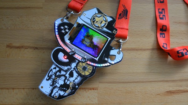
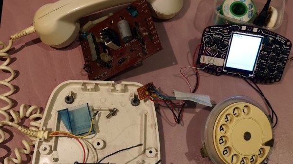
It’s a trend that [Dan] has reversed though, with his rotary dial phone brought to life with an EMF Tilda MkIV. This was the badge from last year’s EMF Camp 2018, and its defining feature was a built-in GSM mobile phone. We didn’t give it a full review at the time because it has problems with the GSM part at the event and it would have been unfair to display what was an amazing badge in a negative light, but once we got it home it was straightforward enough to put a commercial SIM in the slot and use the public networks with it.
[Dan]’s phone is an Eastern European model that came to him through his grandfather. Inside it’s a relatively conventional design, into which he’s patched a couple of the Tilda’s I/O lines from the dial through a debounce circuit. But simply selecting a couple of lines wasn’t enough, as most of those on its expansion port come via a port expander. He needed inputs that could generate an interrupt, so he hijacked a couple from the on-board joystick. He’s included Python code which you can see in action in the video below. It’s important to note that he’s yet to hook up the audio to the badge so this is a work in progress, but it’s an interesting project nevertheless.
Rotary phones hold a special place among hardware hackers, we’ve featured many projects including them. This isn’t the first GSM rotary phone we’ve brought you, and don’t forget they can also talk via Bluetooth.
Continue reading “A Conference Badge Breathes Life Into A Rotary Phone”