When the topic is radiation detection, thoughts turn naturally to the venerable Geiger-Müller tube. It’s been around for ages, Russian surplus tubes are available for next to nothing, and it’s easy to use. But as a vacuum tube it can be somewhat delicate, and the high voltages needed to run it can be a little on the risky side.
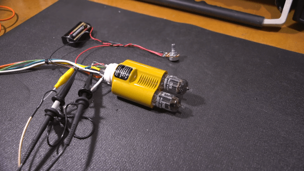
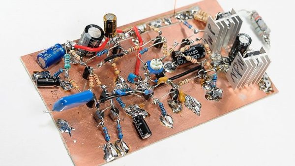
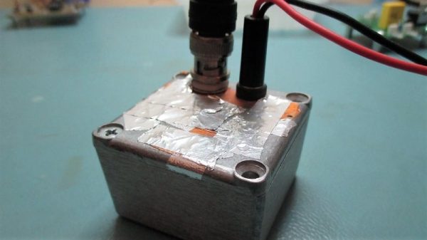
Luckily, there are other ways to see what’s going on in the radioactive world, like this semiconductor radiation detector. [Robert Gawron] built it as a proof-of-concept after having built a few G-M tube detectors before. His solid-state design relies on a reverse-biased photodiode conducting when ionizing radiation hits the P-N junction. The tiny signal is amplified by a pair of low-noise op-amps and output to a BNC connector. The sensor’s analog output is sent to an oscilloscope whose trigger out is connected to a Nucleo board for data acquisition. The Nucleo is in turn connected to a Raspberry Pi for totalizing and logging. It’s a complicated chain, but the sensor appears to work, even detecting alpha emissions from thoriated TIG electrodes, a feat we haven’t been able to replicate with our G-M tube counter.
[Robert]’s solid-state detector might not be optimal, but it has promise. And we have seen PIN diodes used as radiation detectors before, too.
[via Dangerous Prototypes]