After swapping the engine out in his scooter, [James Stanley] made an unfortunate discovery. The speedometer was digitally controlled, and while the original engine had a sensor which would generate pulses for it to interpret, his new engine didn’t. Learning that the original sensor would pull the signal wire to ground each time it detected a tooth of one of the spinning gears, [James] reasoned he needed to find a way to detect the scooter’s speed and create these pulses manually.
To find the scooter’s speed, he installed a magnet on the front wheel and a hall effect sensor on the fork to detect each time it passed by. Since the wheel is of a known circumference, timing the pulses from the sensor allows calculation of the current speed. A GPS receiver could be used if you wanted fewer wires, but the hall effect sensor on the wheel is simple and reliable. With the speed of the scooter now known, he needed to turn that into a signal the speedometer understands.
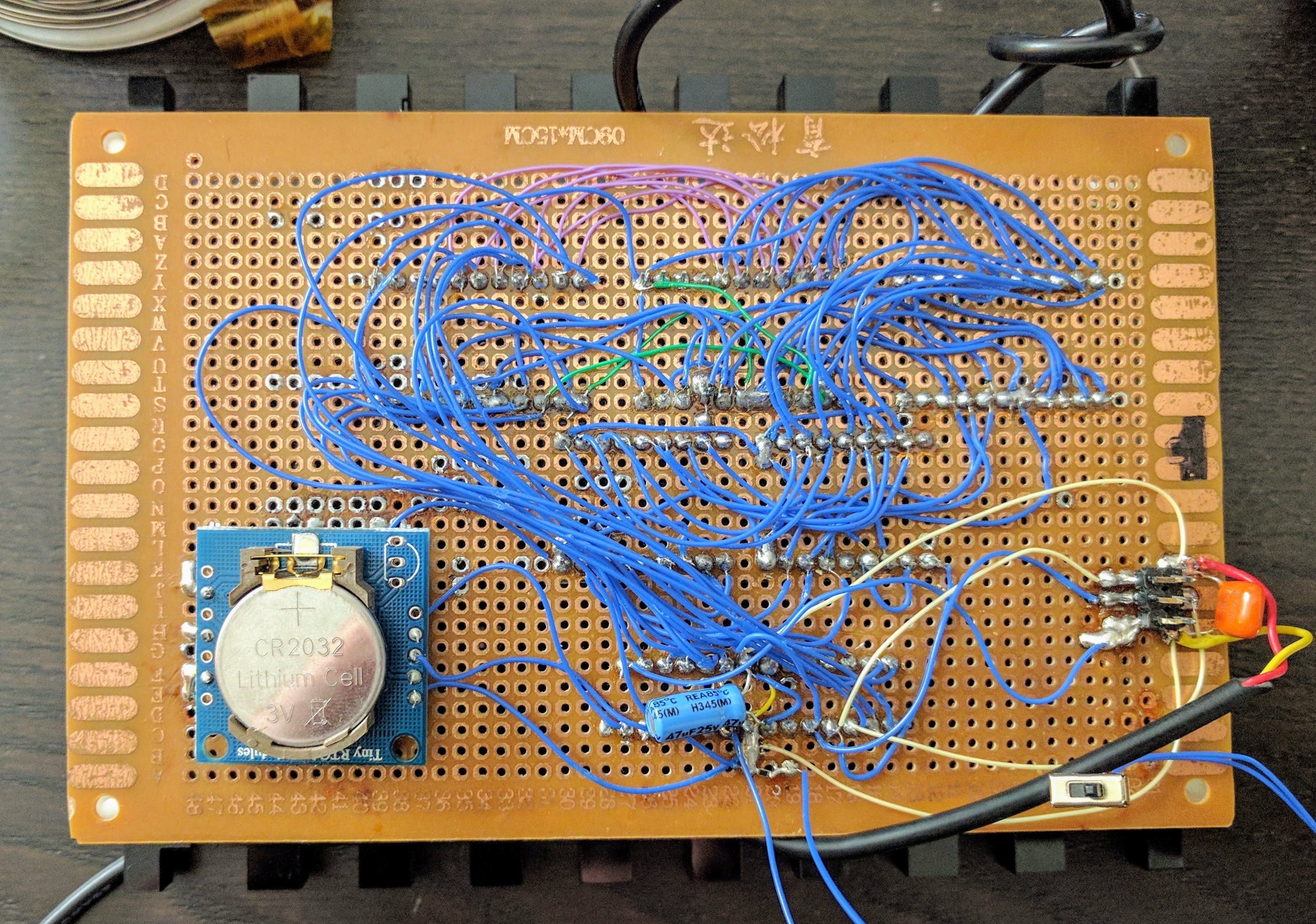
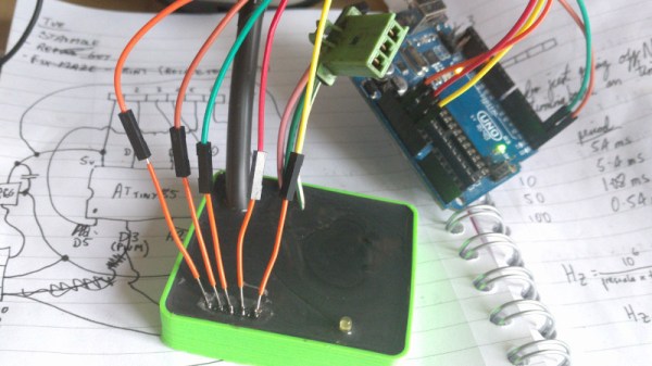
[James] wrote a program for an ATmega that would take the input from the wheel sensor and use it to create a PWM signal. This PWM signal drives a transistor, which alternates the speedometer sensor wire between low and floating. With a bit of experimentation, he was able to come up with an algorithm which equated wheel speed to the gearbox speed the speedometer wanted with accuracy close enough for his purposes.
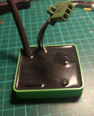
While the software side of this project is interesting in its own right, the hardware is an excellent case study in producing robust electronic devices suitable for use on vehicles. [James] 3D printed a shallow case for the circuit board, and potted the entire device with black polyurethane resin. He even had the forethought to make sure he had a debugging LED and programming connector before he encapsulated everything (which ended up saving the project).
While the specific scenario encountered by [James] is unlikely to befall others, his project is an excellent example of not only interfacing with exiting electronics but producing rugged and professional looking hardware without breaking the bank. Even if scooters aren’t your thing, there are lessons to be learned from this write-up.
For all you two wheeled hackers out there, we’ve covered similar projects designed for bicycles, as well as some very slick digital speedometer mods for motorcycles.