These Lessons Were Learned In Enclosure Design, But Go Far Beyond

[Foaly] has been hard at work making an open-source long range camera remote, and recently shared a deeply thoughtful post about how it is never too early to consider all aspects of design, lest it cost you in the end. It all started with designing an enclosure for a working prototype, and it led to redesigning the PCB from scratch. That took a lot of guts, and we recommend you make some time to click that link and read up on what he shared. You’ll either learn some valuable tips, or just enjoy nodding sagely as he confirms things you already know. It’s win-win.

Note the awkward buttons right next to the antenna connector, for example.

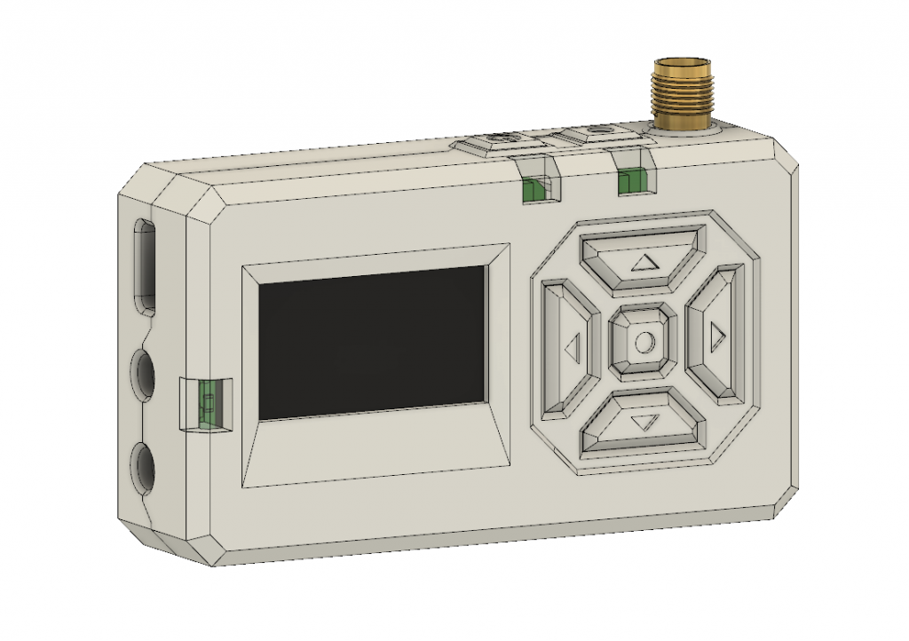
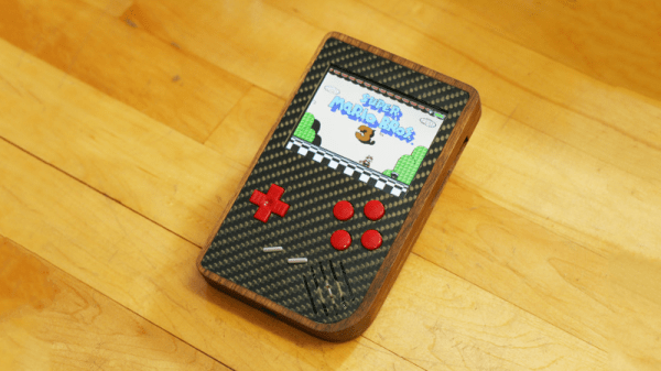
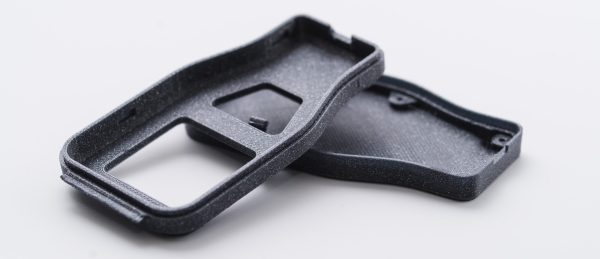
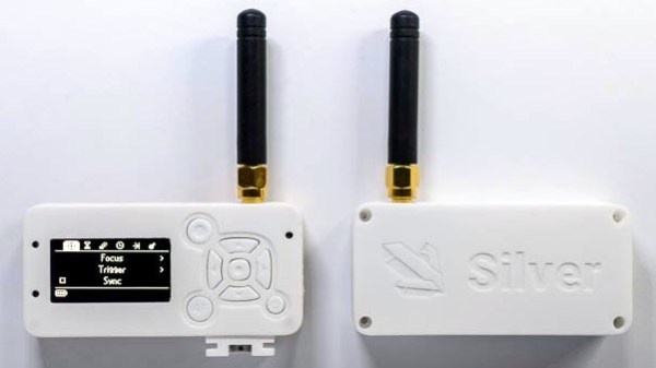
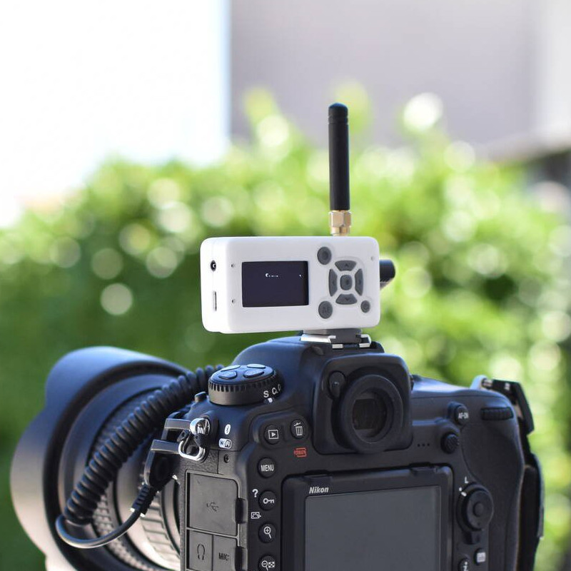
The project in question is Silver, and calling it a camera remote is selling it a bit short. In any case, [Foaly] had a perfectly serviceable set of prototypes and needed a small batch of enclosures. So far so normal, but in the process of designing possible solutions, [Foaly] ran into a sure-fire sign that a project is in trouble: problems cropping up everywhere, and in general everything just seeming harder than it should be. Holding the mounting-hole-free PCB securely never seemed quite right. Buttons were awkward to reach, ill-proportioned, and didn’t feel good to use. The OLED screen’s component was physically centered, but the display was off-center which looked wrong no matter how the lines of the bezel were sculpted. The PCB was a tidy rectangle, but the display ended up a bit small and enclosures always looked bulky by the time everything was accounted for. The best effort is shown here, and it just didn’t satisfy.

[Foaly] says the real problem was that he designed the electronics and did the layout while giving some thought (but not much thought) to their eventual integration into a case. This isn’t necessarily a problem for a one-off, but from a product design perspective it led to so many problems that it was better to start over, this time being mindful of how everything integrates right from the start: the layout, the components, the mechanical bits, the assembly, and the ultimate user experience. The end result is wonderful, and we’re delighted [Foaly] took the time to document his findings.

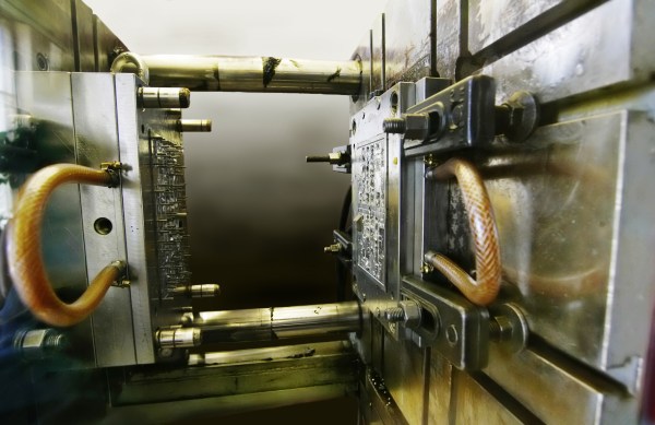
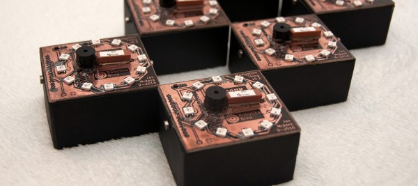
Enclosure design is a big deal and there are many different ways to go about it. For a more unique spin, be sure to check out our how-to make enclosures from the PCBs themselves. For a primer on more traditional enclosure manufacture and design, take a few minutes to familiarize yourself with injection molding.

Pi Handheld With A Mindblowing Enclosure

The Raspberry Pi is possibly the world’s most popular emulation platform these days. While it was never intended to serve this purpose, the fact remains that a small, compact computer with flexible I/O is ideally suited to it. We’ve featured a multitude of builds over the years using a Pi in a mobile form factor to take games on the go. [Michael]’s build, however, offers a lot more than a few Nintendo ROMs and some buttons from eBay. It’s a tour de force in enclosure design.

The build starts with the electronics. In 2017 it’s no longer necessary to cobble together five different accessory boards to handle the controls, battery charging, and display. Boards like Kite’s Super All In One exist, handling everything necessary for a handheld game console. With this as a starting point, he then set out to recreate Nintendo’s classic Game Boy, with a few tweaks to form and function.

It’s a textbook example of smart planning, design, and execution. We are taken through the process of creating the initial CAD drawings, then combining 3D printed parts with wood and carbon fibre for a look that is more akin to a high-end piece of hi-fi gear than anything related to gaming. The attention to detail is superb and the write-up makes it look easy, while [Michael] shares tips on how to safely cut carbon fibre to make your own buttons.

The final results are stunning, and it’s a great example of why a fine piece of wood is always a classy way to go for an enclosure. For another great example, try this walnut keyboard, or check out the roots of the Raspberry Pi Game Boy movement.

Designing Your Project To Scale: Crossing The Chasm

Hackaday is all about the neat hacks and the repurposing of old components into new projects, but many people then try to take those projects and turn them into businesses. We’ve seen lots of people offer their stuff as kits and sell them on Tindie, with the rare few going on to develop a consumer electronic product at scale.

The Hackaday Prize 2017 Best Product highlights this journey. “Scale” itself is a vague term, but essentially it means to be able to produce enough to meet market demand. We hope that market demand is roughly 7 billion units, purchasing yearly, but the reality is that it is somewhere between 1 and a few hundred thousand, with very big differences in manufacturing at each order of magnitude. So how do you start with a proof of concept and design your product from the very beginning to be optimized to scale to meet whatever demand you can handle?

Continue reading “Designing Your Project To Scale: Crossing The Chasm”

Practical Enclosure Design, Optimized For 3D Printing

[3D Hubs] have shared a handy guide on designing practical and 3D printing-friendly enclosures. The guide walks through the design of a two shell, two button remote control enclosure. It allows for a PCB mounted inside, exposes a USB port, and is optimized for 3D printing without painting itself into a corner in the process. [3D Hubs] uses Fusion 360 (free to hobbyists and startups) in their examples, but the design principles are easily implemented with any tool.

One of the tips is to design parts with wall thicknesses that are a multiple of the printer’s nozzle diameter. For example, a 2.4 mm wall thickness may sound a bit arbitrary at first, but it divides easily by the typical FDM nozzle diameter of 0.4 mm which makes slicing results more consistent and reliable. Most of us have at some point encountered a model where the slicer can’t quite decide how to handle a thin feature, delivering either a void between perimeters or an awkward attempt at infill, and this practice helps reduce that. Another tip is to minimize the number of sharp edges in the design, because rounded corners print more efficiently and with smoother motions from the print head.

The road to enclosures has many paths, including enclosures made from FR4 (aka PCB material) all the way down to scrap wood with toner transfer labeling, and certainly desktop 3D printing has been a boon to anyone who’s had to joylessly drill and saw away at a featureless plastic box.

Tools Of The Trade — Injection Molding

Having finished the Tools of the Trade series on circuit board assembly, let’s look at some of the common methods for doing enclosures. First, and possibly the most common, is injection molding. This is the process of taking hot plastic, squirting it through a small hole and into a cavity, letting it cool, and then removing the hardened plastic formed in the shape of the cavity.

The machine itself has three major parts; the hopper, the screw, and the mold. The hopper is where the plastic pellets are dumped in. These pellets are tiny flecks of plastic, and if the product is to be colored there will be colorant pellets added at some ratio. The hopper will also usually have a dehumidifier attached to it to remove as much water from the pellets as possible. Water screws up the process because it vaporizes and creates little air bubbles.

Next the plastic flecks go into one end of the screw. The screw’s job is to turn slowly, forcing the plastic into ever smaller channels as it goes through a heating element, mixing the melted plastic with the colorant and getting consistent coloring, temperature, and ever increasing pressure. By the time the plastic is coming out the other end of the screw, and with the assistance of a hydraulic jack, it can be at hundreds of tons of pressure.

Finally, the plastic enters the mold, where it flows through channels into the empty cavity, and allowed to sit briefly to cool.  The mold then separates and ejector pins push the part out of the cavity.

Continue reading “Tools Of The Trade — Injection Molding”

Navigation Thing: Four Days, Three Problems, And Fake Piezos

The Navigation Thing was designed and built by [Jan Mrázek] as part of a night game activity for high school students during week-long seminar. A night-time path through a forest had stations with simple tasks, and the Navigation Thing used GPS, digital compass, a beeper, and a ring of RGB LEDs to provide a bit of “Wow factor” while guiding a group of students from one station to the next. The devices had a clear design direction:

“I wanted to build a device which a participant would find, insert batteries, and follow the beeping to find the next stop. Imagine the strong feeling of straying in the middle of the night in an unknown terrain far away from civilization trusting only a beeping thing you found. That was the feeling I wanted to achieve.”

The Navigation Things (there are six in total) guide users to fixed waypoints with GPS, a digital compass, and a ring of WS2812 LEDs — but the primary means of feedback to the user is a beeping that gets faster as you approach the destination. [Jan] had only four days to make all six units, which was doable. But as most of us know, delivering on a tight deadline is often less about doing the work you know about, and more about effectively handling the unexpected obstacles that inevitably pop up in the process.

Continue reading “Navigation Thing: Four Days, Three Problems, And Fake Piezos”

DIY Thermal Insert Press

You might not know what a threaded insert is, but chances are you’ve seen one before. Threaded inserts are small metal (typically brass) inserts that are pressed into plastic to give a strong point of attachment for bolts and screws. These inserts are a huge step up from screwing or bolting directly into tapped plastic holes since the brass threads are very strong compared to the plastic. The only major downside to these inserts is that the press to install them is incredibly expensive. Thankfully, [Alex Rich] came up with a cheap solution: a modified soldering iron mounted to an Arbor press.

Commercial threaded insert presses typically use ultrasonic welding or heat welding to fuse inserts with plastic. [Alex] chose the simple route and went with heat welding, which (as you might imagine) is way simpler than ultrasonic welding. To provide the heat, [Alex] mounted a 100W Weller soldering iron to the press, which he says handles the impact with no problem. Unfortunately the copper tips of the Weller just wouldn’t hold up to the impact, so [Alex] made his own tips out of some brass he turned on a lathe.

If, like most people, you don’t have the capability of making injection-molded cases, let alone an Arbor press on hand, you’re not out of luck! Using this same technique people have successfully added thermal inserts to 3d-printed parts using a soldering iron and much smaller DIY presses. Have any ideas on how you could use thermal inserts in your 3d prints? Let us know in the comments.